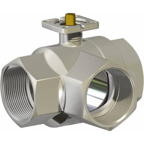
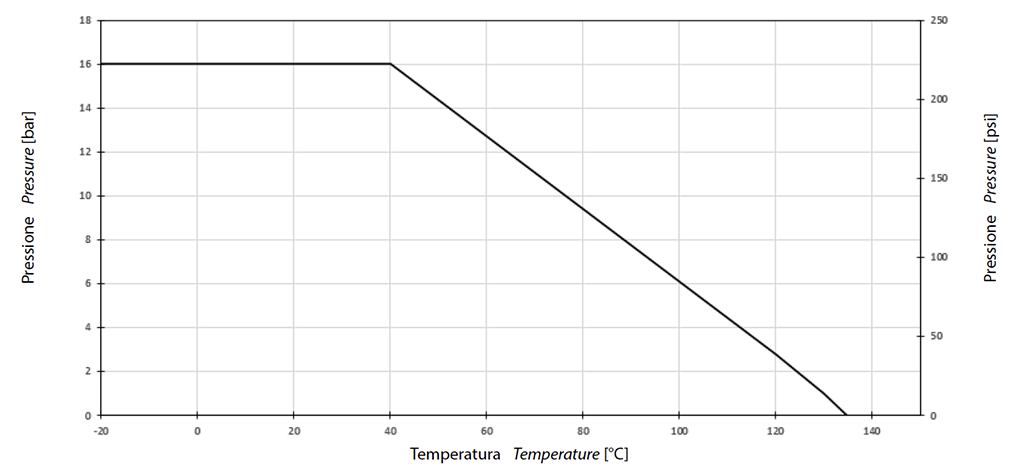
GENERAL FEATURES: • The valve is suitable for medium pressures with non aggressive fluids. The valve can be used as diverter only the in let can be from central way only, see plane. • Working temperature: from -20°C to + 120°C • Working pressure: 16 bar max, see diagram • Fluid range: air, water, oil, gas, petroliferous and petrochemical products. • Threaded ends as per ISO 7/1 and NPT specifications. • ISO 5211 flange connection.
ON REQUEST: • For other applications, please contact our sales department.
CERTIFICATIONS: • According to 2014/68/EU “PED” • ATEX version in conformity with directive 2014/34/EU on request
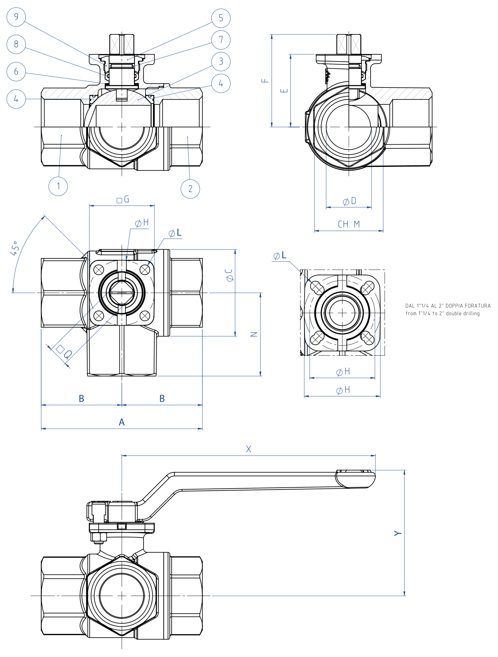
DIMENSIONS
SIZE
øD
A
B
øc
N
□Q
E
F
□G
øH
ISO
øL
ch.M
X
Y
DN [mm]
[inch]
ISO 7/1
NPT
ISO 7/1
NPT
DN 10
3/8"
10
69
62
33
31
31,8
33
9
30,5
38,4
36
36
F03
5,5
25
140
58,5
DN 15
1/2"
15
69
62
33
31
31,8
33
9
30,5
38,4
36
36
F03
5,5
25
140
58,5
DN 20
3/4"
20
77
68
38
34
40
38
11
36,3
47,1
36
36
F03
5,5
31
140
64,5
DN 25
1"
25
89
79,5
46
39,8
48
46
11
40,2
50,9
36
36
F03
5,5
38
140
68,5
DN 32
1" 1/4
32
103
92
54
46
60
54
11
51,5
62,5
42
36/42
F03/F04
5,5
47
140
80
DN 40
1" 1/2
40
114
102
61
51
70,6
61
11
58
69
42
36/42
F03/F04
5,5
54
140
86
DN 50
2"
50
134
116
73
58
86,5
73
11
65,3
76,3
46
42/50
F04/F05
5,5/6,5
66
140
93,5
MATERIALS
1
Body*
Brass
EN 12165 CW617N
2
Threaded ends*
Brass
EN 12165 CW617N
3
Ball
Brass chromium plated
EN 12164 CW614N
4
Seals
P.T.F.E.
5
Shaft
Brass
EN 12164 CW614N
6
Antifriction rings
P.T.F.E.
7
O-ring
FKM
8
Shaft seal
P.T.F.E.
9
Gland nut*
Brass
EN 12164 CW614N
*Surface treatment: bright nickel plating
Pressure/temperature diagram
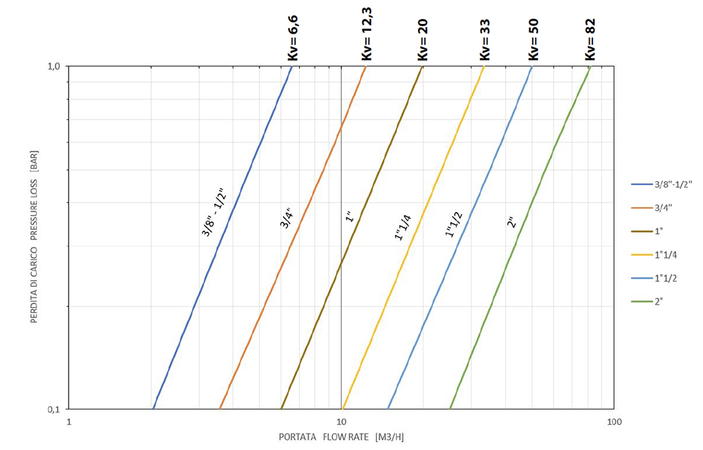
Flow/pressure loss diagram and Kv nominal coefficient
Kv is the coefficient, expressed in m3/h (with water at 15°C) causing a pressure loss of 1 bar.
BREAKAWAY TORQUES Nm
SIZE
DN 10 3/8"
DN 15 1/2"
DN 20 3/4"
DN 25 1"
DN 32 1"1/4
DN 40 1"1/2
DN 50 2"
PN 16 bar
4
4
5
8
11
16
23
Torque can vary depending on temperature and type of fluid; a safety factor of 1.4 must be applied. Torque can drop on high frequency of operations. The actuator/valve sizing, indicated on the following pages, are based for valves to be used with liquids or gaseous fluids, clean, and for medium temperatures. For further information, or different uses please contact our sales department.
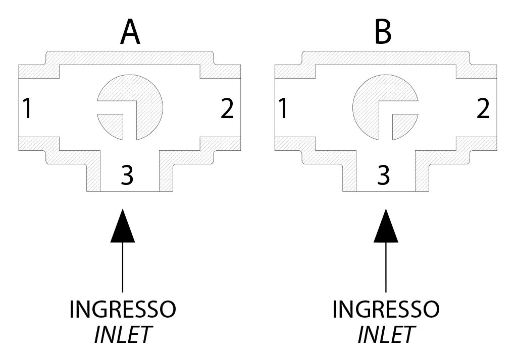
Plan for "L"
N.B.: “A” must be the rest position of the ball with SR FAIL CLOSE actuator. “B” must be the rest position of the ball with SR FAIL OPEN actuator.