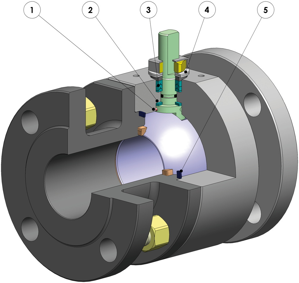
1. Antistatic device (electrical continuity between ball, stem and body) Static electricity is avoided which can cause sparks and fire in an inflammable/explosive environment Contact safety throughout the entire life of the valve
2. Double antifriction washer Less Breakaway Torque is granted Less wear comparing with the execution with the single washer
3. "V" seals pack; 3 seals + o-ring It ensures a perfect tightness even after a high number of cycles
4. Spring washer on the shaft seal Guarantee of the recovery of the gap due to the wear caused by the rotational movement of the shaft avoiding leakage towards the outside part. Allow to maintain energized the "chevron" seals (V), thus avoiding any leakage to the outside, against huge temperature excursions
5. Stretch Graphite seal Tightness towards outside is granted, independently by the thermal excursions to which the valve is subjected Greater precision in the alignment of axes due to a unique positioning in the process machining from raw material to finished valve Longer lifetime of the valve Less breakaway torque
Easy maintainance directly on site Reduced maintainance costs
Valve body in carbon steel made with NACE certified material as standard Greater corrosion resistance Greater ductility of the material
100% in- house manufacturing process technology Maximum control and accuracy in all the stages of the manufacturing process Flexibility in supply quickly special executions requested by customers
"Fire safe" Certificate Guarantees the tightness of the valve also in case of fire
ATEX Certificate Installation is possible in a potential explosive environment
TA LUFT fugitive emission Certificate High level of safety of the tightness towards the outside is granted
PED Certificate Full compliance with European Safety Standards for Pressure Equipment
UP to SIL 3 certified Guarantee of the high level of functional safety
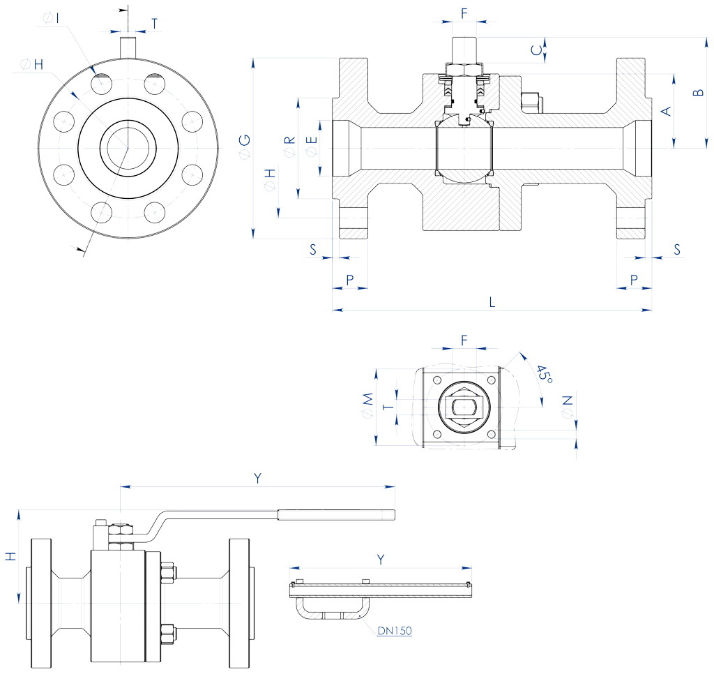
DIMENSIONS
SIZE
ANSI
A
B
C
∅E
Att. ISO
∅M
∅N
F/T
∅G
∅R
S
∅H
HOLES N°
∅I
P
Kg
L
H
Y
LEVER KIT
SEALS KIT
DN [mm]
[inch]
20x15
3/4”x1/2”
600
40
54,5
9,6
19
F04
42
M5
12/8
118
42,9
6,4
82,6
4
19
22,6
6,8
190
80
150
KLV58006
KGBV472040
25x20
1”x3/4”
600
45
57,5
9,6
25
F04
42
M5
12/8
125
50,8
6,4
88,9
4
19
24,4
8
216
88
150
KLV58006
KGBV472050
32x25
1”1/4x1”
600
50
71,5
14,6
32
F05
50
M6
16/10
135
63,5
6,4
98,6
4
19
27,4
10,8
229
95
275
KLV58008
KGBV472060
40x32
1”1/2x1”1/4
600
55
76,5
14,6
38
F05
50
M6
16/10
155
73
6,4
114,3
4
22
29,1
14,1
241
100
275
KLV58008
KGBV472070
50x40
2”x1”1/2
600
68
98,5
20,4
51
F07
70
M8
22/14
165
91,9
6,4
127
8
19
32,1
21,5
292
120
350
KLV58010
KGBV472080
65x50
2”1/2x2”
600
74
107,5
20,4
64
F07
70
M8
22/14
190
104,6
6,4
149,4
8
22
36,1
28,8
330
129
350
KLV58010
KGBV472090
80x65
3”x2”1/2
600
94
144
25,1
76
F10
102
M10
30/18
210
127
6,4
168,1
8
22
39,1
49
356
180
450
KLV58012
KGBV472100
100x80
4”x3”
600
101,5
151,5
25,1
102
F10
102
M10
30/18
275
157,2
6,4
215,9
8
25,5
45,1
75,3
432
188
450
KLV58012
KGBV472110
150x100
6”x4”
600
126
196,5
40,5
152
F14
140
M16
45/30
357
215,9
6,4
292,1
12
28,6
54,4
160
559
243
800
KLV58014
KGBV472120
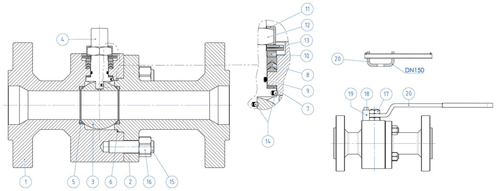
MATERIALS
ANSI 600 FROM BAR
N°
Description
316 Stainless steel
1
Body
ASTM A 182 F316 / A479TP.316 (1.4401 / X5CrNiMo 17-12-2)
2
Connector
3
Ball
ASTM A351 CF8M (1.4408/Gx5CrNiMo19-12-2)
4
Stem
A564 TP.630 (17-4PH)
5*
Seat
DEVLON (.)
6*
Body-Connector gasket
GRAFOIL
7*
Stem lower sealing
Modified PTFE (.) (1)
8*
Chevron seals
Modified PTFE (.)
9*
Stem o-ring
FKM (.)
10
Packing gland ring
304 S.S.
11
Stop nut plate
304 S.S.
12
Stem nut
Carbon steel galvanized (x)
13
Springs washer
Carbon steel galvanized (xx)
14
Antistatic device
316 S.S.
15
Stud bolt
ASTM A193-B8
16
Nut
ASTM A194-Gr.8
17
Lock nut
Carbon steel galvanized
18
Holder screw
A2-70 (304 S.S.)
19
Holder screw
Carbon steel galvanized (x)
20
Lever
Fe37 galvanized (x)
* Components of seals kit
Available on request: (x): 304 s.s. (xx): 301 s.s. (1): for DN≤40x32 available only in DEVLON (.): Other materials available on request
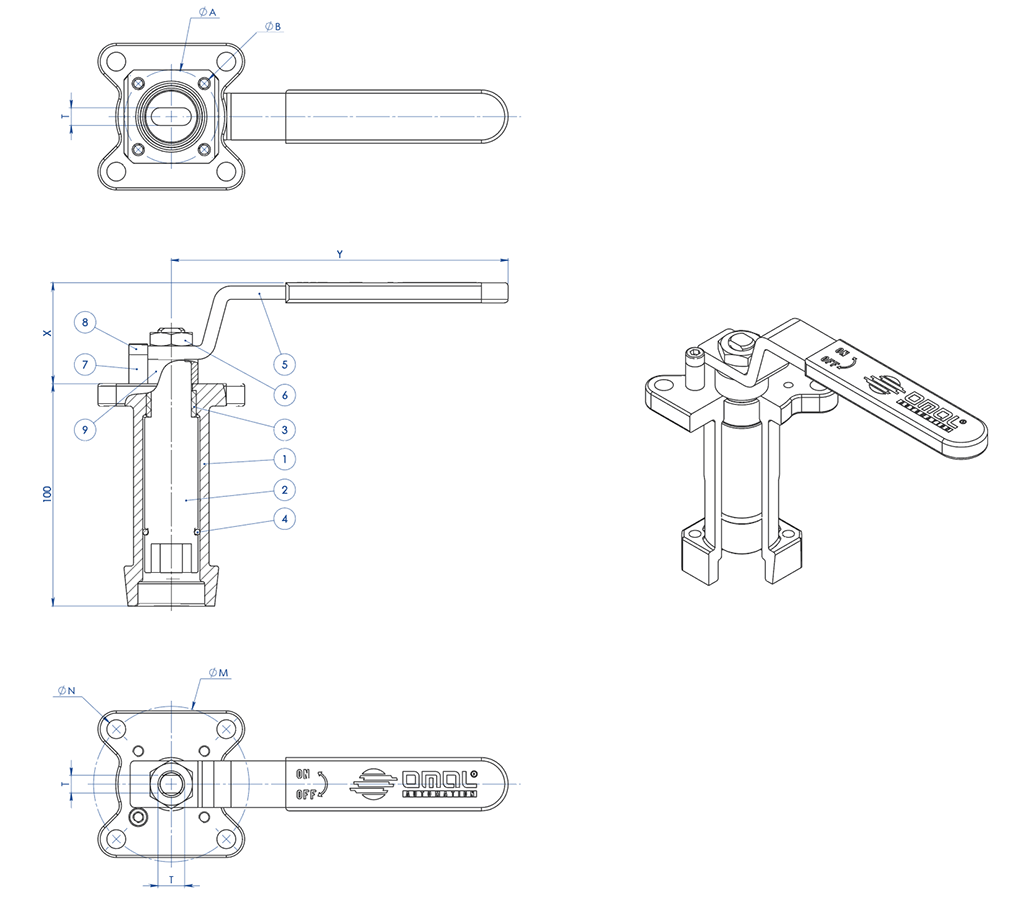
CASTING STEM EXTENSION WITH LEVER
MATERIALS
PART. N°
DESCRIPTION
MATERIAL
1
Extension
AISI304 S.S.
2
Pin
AISI 430 F
3
Bush
DELRIN
4
O-RING
NBR
5
Lever
Fe 37 galvanized (*)
6
Nut
galvanized carbon steel (*)
7
Holder Lever
galvanized carbon steel (*)
8
Holder screw
A2-70
9
Spacer
PTFE Carbon Filled
(*): On request available in Aisi 304 s.s.
DIMENSIONS
ISO VALVE
ØA
ØB
ØM
ØN
F/T
X
Y
F03
36
5,5
36
5,5
10/6
38,5
141,5
F04
42
5,5
42
M5
12/8
45,5
151,5
F05
50
6,5
50
6,5
16/10
48,5
276,5
F07
70
8,5
70
8,5
22/14
57,5
351,5
F10
102
11
102
11
30/18
79,5
451,5
NOTE: Code of the spindle extension depending from drive’s type and valve’s connection; to be requested at the order.
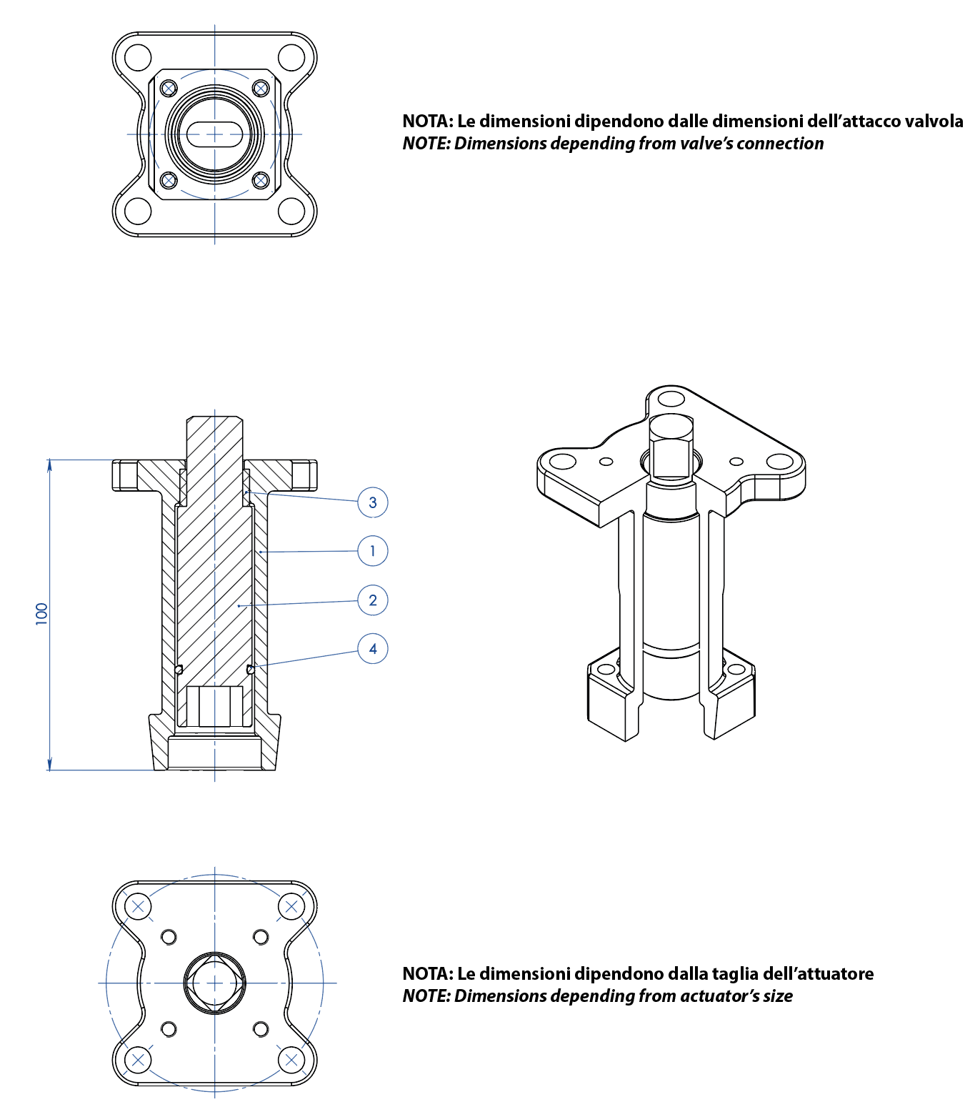
CASTING STEM EXTENSION FOR ACTUATORS
MATERIALS
PART. N°
DESCRIPTION
MATERIAL
1
Extension
ASTM A351 CF8M
2
Pin
AISI 430 F
3
Bush
DELRIN
4
O-RING
NBR
NOTE: Code of the spindle extension depending from drive’s type and valve’s connection; to be requested at the order
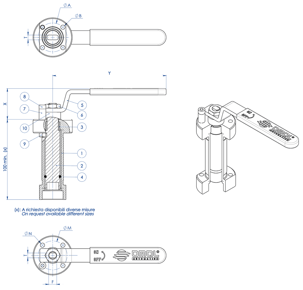
WELDED STEM EXTENSION WITH LEVER
MATERIALS
PART. N°
DESCRIPTION
MATERIAL
1
Extension
304 s.s.
2
Pin
AISI 430 F
3
Bush
DELRIN
4
O-Ring
NBR
5
Lever
Fe 37 galvanized (*)
6
Nut
galvanized carbon steel (*)
7
Holder Lever
galvanized carbon steel (*)
8
Holder screw
A2-70
9
Holder nut
A2-70 (**)
10
Spacer
PTFE Carbon Filled
(*): On request available in Aisi 304 s.s.
(**): No available on valves with Iso connection F04
DIMENSIONS
ISO VALVE
ØA
ØB
ØM
ØN
F/T
X
Y
F03
36
5,5
36
5,5
10/6
38,5
141,5
F04
42
5,5
42
M5
12/8
45,5
151,5
F05
50
6,5
50
6,5
16/10
48,5
276,5
F07
70
9
70
9
22/14
57,5
351,5
F10
102
11
102
11
30/18
79,5
451,5
NOTE: Code of the stem extension depending from drive’s type and valve’s connection; to be requested at the order.
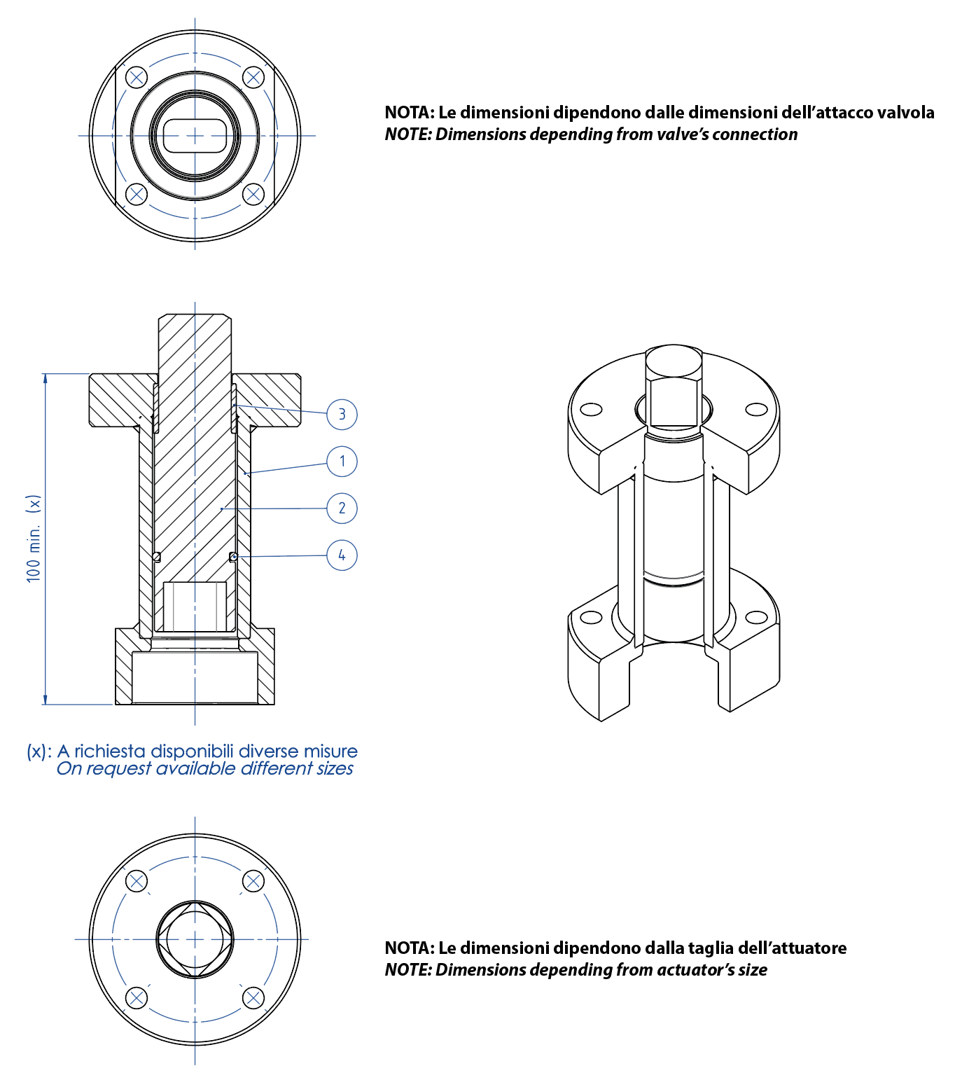
WELDED STEM EXTENSION FOR ACTUATORS
MATERIALS
PART. N°
DESCRIPTION
MATERIAL
1
Extension
304 S.S.
2
Pin
AISI 430 F
3
Bush
DELRIN
4
O-RING
NBR
NOTE: Code of the stem extension depending from drive’s type and valve’s connection; to be requested at the order.
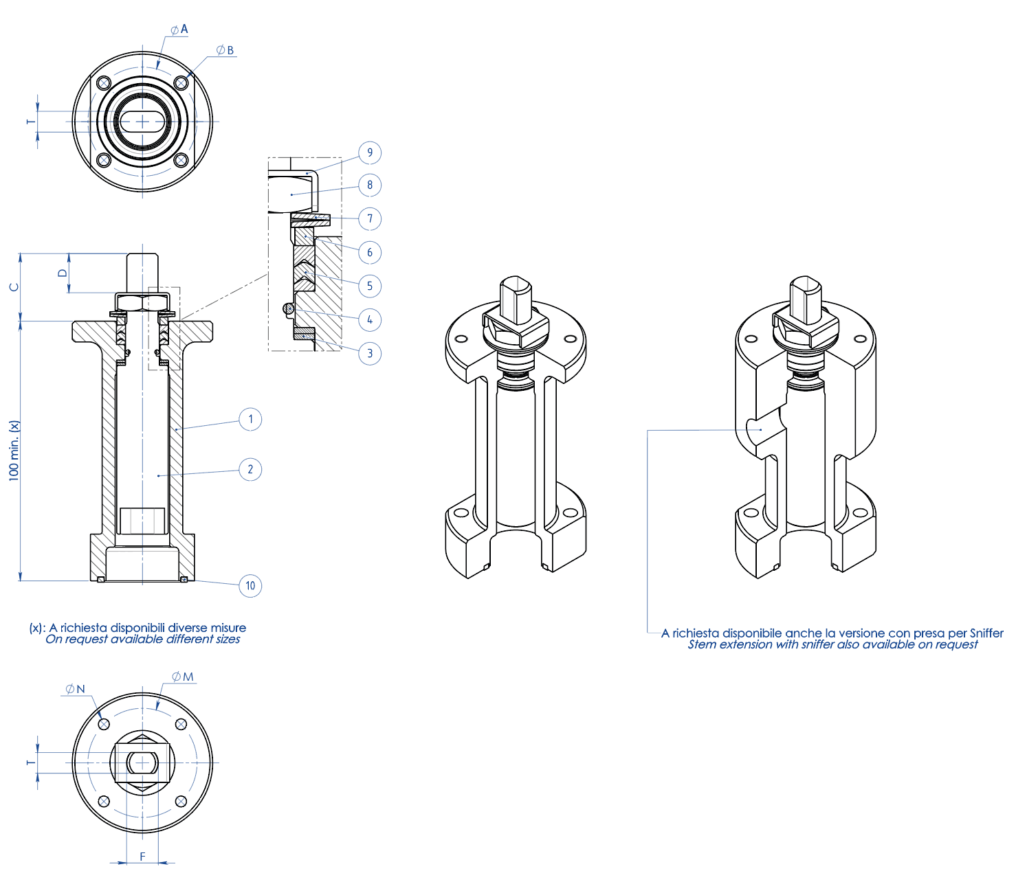
STEM EXTENSION WITH ADDITIONAL SEAL
MATERIALS
PART. N°
DESCRIPTION
MATERIAL
1
Extension
304 s.s.
2
Pin
A564 TP.630 (17-4ph)
3
Bottom Sealing
TFM1600
4
O-Ring
FKM
5
Chevron Ring
TFM1600
6
Packing Gland Ring
304 s.s.
7
Spring Washer
50CrV4 Galvanized
8
Stem Nut
UNI 3740-1 6S Galvanized
9
Stop Nut Plate
304 s.s.
10
Gasket
GRAFOIL
DIMENSIONS
ISO VALVE
ØA
ØB
ØM
ØN
F/T
C
D
F03
36
5,5
36
M5
10/6
20
10,2
F04
42
5,5
42
M5
12/8
26
15,1
F05
50
6,5
50
M6
16/10
35
21,2
F07
70
8,5
70
M8
22/14
47,5
28,4
F10
102
10,5
102
M10
30/18
61
35,2
NOTE: Code of the spindle extension depending from drive’s type and valve’s connection; to be requested at the order.