TECHNICAL FEATURES Metering rotation angle: 45° max. Max. rotation angle: 92° (-1°, +91°) Torque (see the corresponding actuator tables). The code numbers after the letters DDN, always correspond to the breakaway torque in Nm at 5,6 bar air supply.
WORKING CONDITION Temperature: from -20°C to +80°C. Air supply: 5,6 bar; maximum 8,4 bar. Actuating media: filtered dry compressed air, not necessarily lubricated. In case of lubricated air, either non detergent oil, NBR compatible oil, must be used.
DATA SHEET
Code
DDN030401S
DDN030402S
DDN060401S
DDN060402S
DDN106401S
DDN240401S
DDN480401S
Size
DDN 30 F03-F05
DDN 30 F04
DDN 60 F04
DDN 60 F05-F07
DDN 106 F05-F07
DDN 240 F07-F10
DDN 480 F10-F12
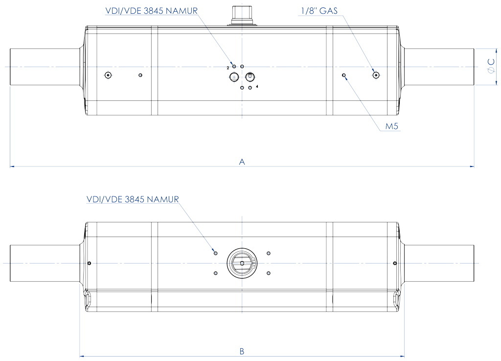
A [mm]
355
355
423
423
502
589
702
B [mm]
245
245
278
278
345
416
491
C [mm]
29
29
29
29
29
40
55
Weight [Kg]
1,8
1,8
2,8
2,8
4,7
8
14,3
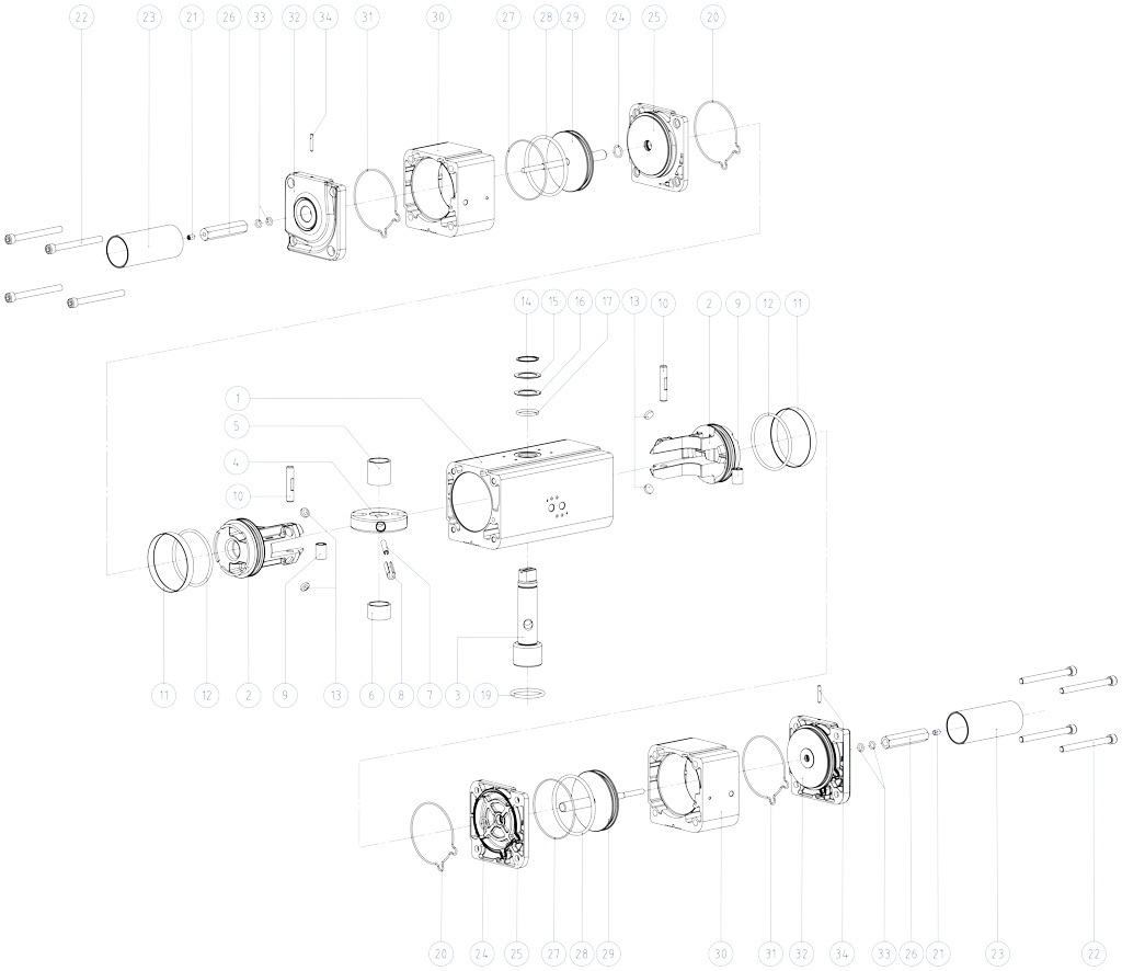
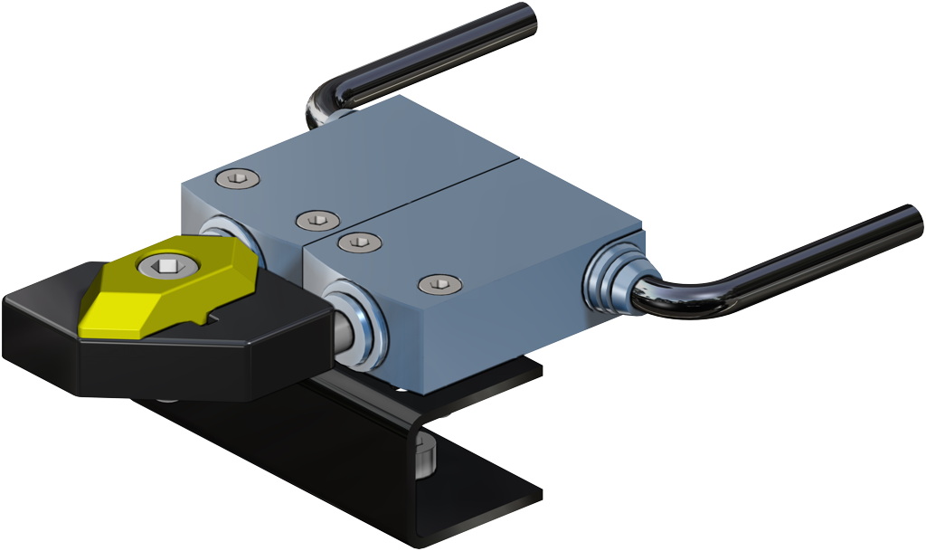
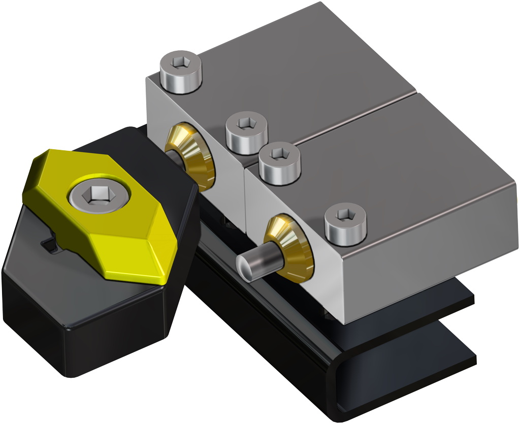
TWO STAGE PNEUMATIC ACTUATOR COMPONENTS SIZE: DDN30 - DDN480
MATERIALS
Pos
Denomination
Q.ty
Material
1
Cylinder
1
Aluminium alloy
2
Piston
2
Aluminium alloy
3
Shaft
1
Stainless steel
4
Scotch yoke
1
Steel alloy
5
Bush
1
Acetalic resin
6
Bush
1
Acetalic resin
7
Int.elastic pin
1
Steel alloy
8
Ext.elastic pin
1
Steel alloy
9
Bush
2
Steel alloy
10
Sleeve
2
Steel alloy
11
Dynamic seal
2
Polyurethan
12
O-ring
2
Nitrilic rubber
13
Support disks
4
P.T.F.E. carbo-graphite filled
14
Seeger
1
Stainless steel
15
Washer
1
Stainless steel
16
Ext.support ring
1
Acetalic resin
17
O-ring
1
FKM
18
Centering ring (OPTIONAL)
1
Aluminium alloy
19
O-ring
1
FKM
20
O-ring
2
Nitrilic rubber
21
Grub screw
2
Stainless steel
22
screws
8
Stainless steel
23
protection
2
Aluminium alloy
24
Support bush
2
FKM
25
Intermediate cap
2
Aluminium alloy
26
Adjusting nut
2
Aluminium alloy
27
O-ring
2
Nitrilic rubber
28
O-ring
2
Nitrilic rubber
29
Auxiliary piston
2
Aluminium alloy
30
Auxiliary cylinde
2
Aluminium alloy
31
O-ring
2
Nitrilic rubber
32
Terminal cap
2
Aluminium alloy
33
O-ring
4
FKM
34
Grub screw
2
Stainless steel
Working plane
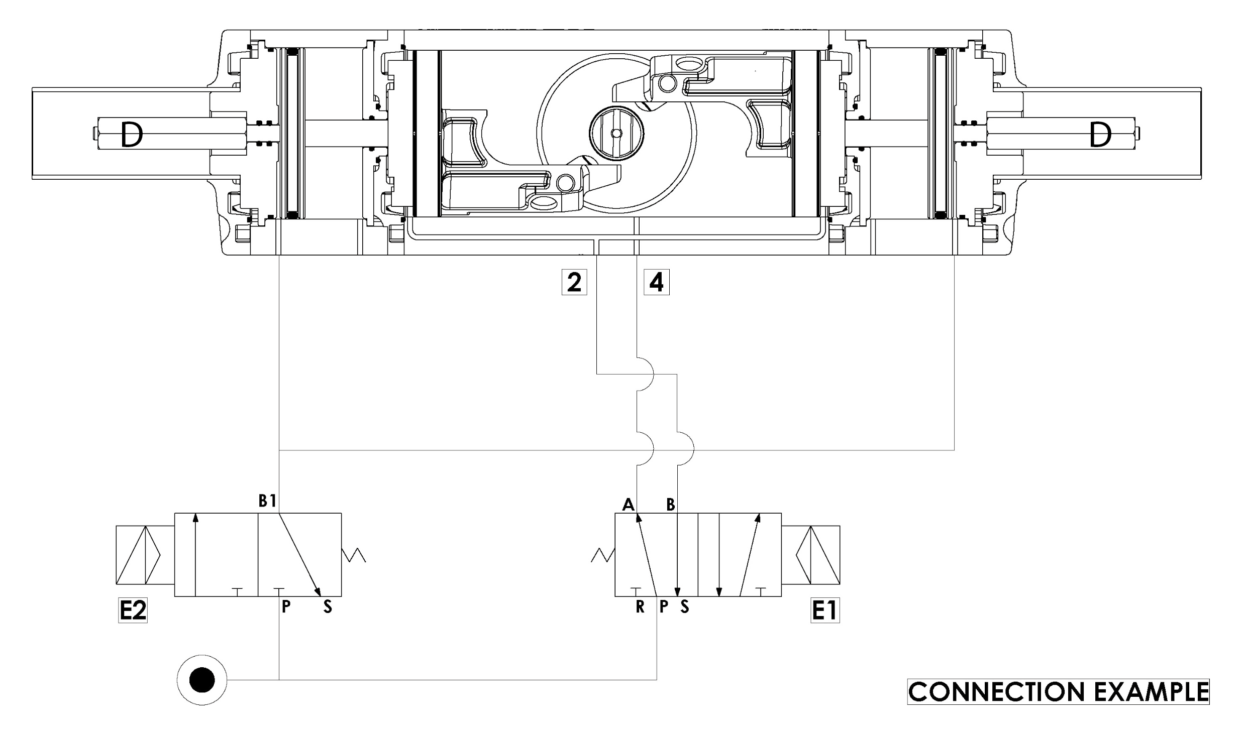
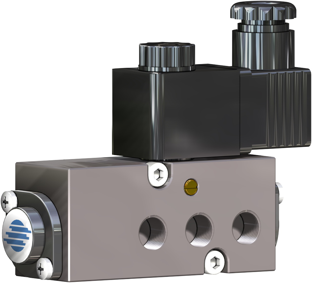
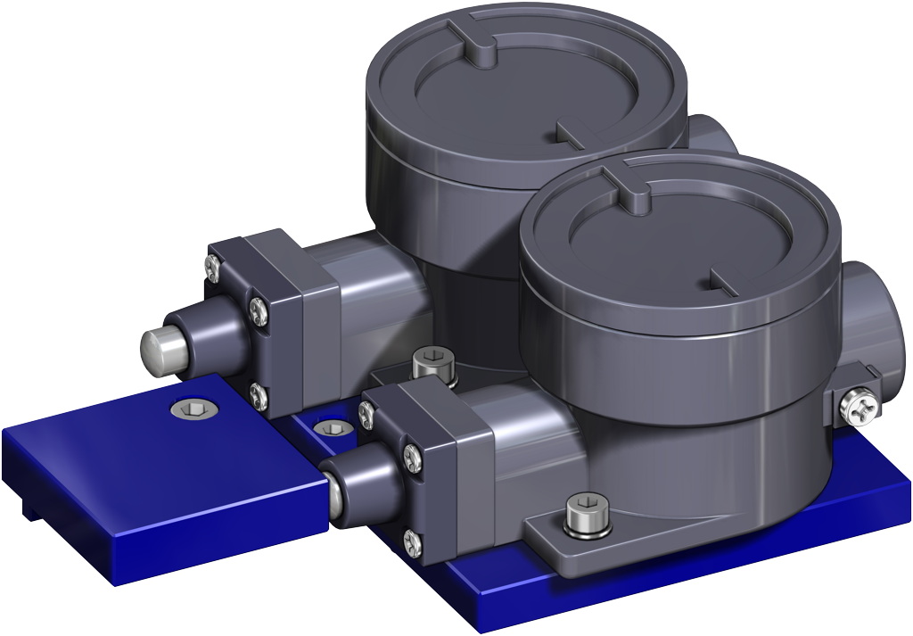
General use and working condition USE: Filling and metering of fluids or solids-mix materials by means of a special metering device. Double acting actuator for fine or rough metering. EXECUTION: According to EN ISO 5211, in compliance with EN 15714-3. WORKING SYSTEM: The basic model consists of an Omal double acting actuator, equipped with two additional cylinders whose inner-pistons, by means of a stroke adjustment device, stop the rotating angle of the actuator to a pre-set position, preventing it from a complete rotation and influencing the total valve flow pressure. This device is driven by two solenoid valves. E1 = 5/2; E2 =3/2. E1 drives the actuator, while E2 drives the two external cylinders. Some examples referring to the valves in the drawing above: - with a completely CLOSED VALVE (0°) You will have: E1: air supply in A, exhausts in B E2: exhausts in B1. - with a completely OPEN VALVE (90°) rough metering You will have: E1: exhausts in A, air supply in B E2: exhausts in B1.
When You reach the desired level, e.g. 90% of the total filling, the rough signal (completely open valve) will turn off and the air, flowing through E2 and then changing the position of E1, will get to the external pistons which will move to the desired rotating angle, e.g. 30° (fine metering), consequently reducing the total valve flow.. With an OPEN VALVE, e.g. 30° fine metering, You will have: E1: air supply in A, exhaust in B; E2: air supply in B1
This intermediate position and the corresponding valve flow pressure will be reproduced, whenever you repeat the process. NOTE: Thanks to control “D”, the desired metering can range from 0° to 45°.When the desired level is the same as the actual one, the fine-metering signal on E2 (exhaust in B1) will turn off; the actuator will start moving and make the valve close, completely. Now the filling and metering process is over. CONCLUSION: “OMAL” device can be assembled wherever you need to furnish exactly the same quantities in long working cycles.
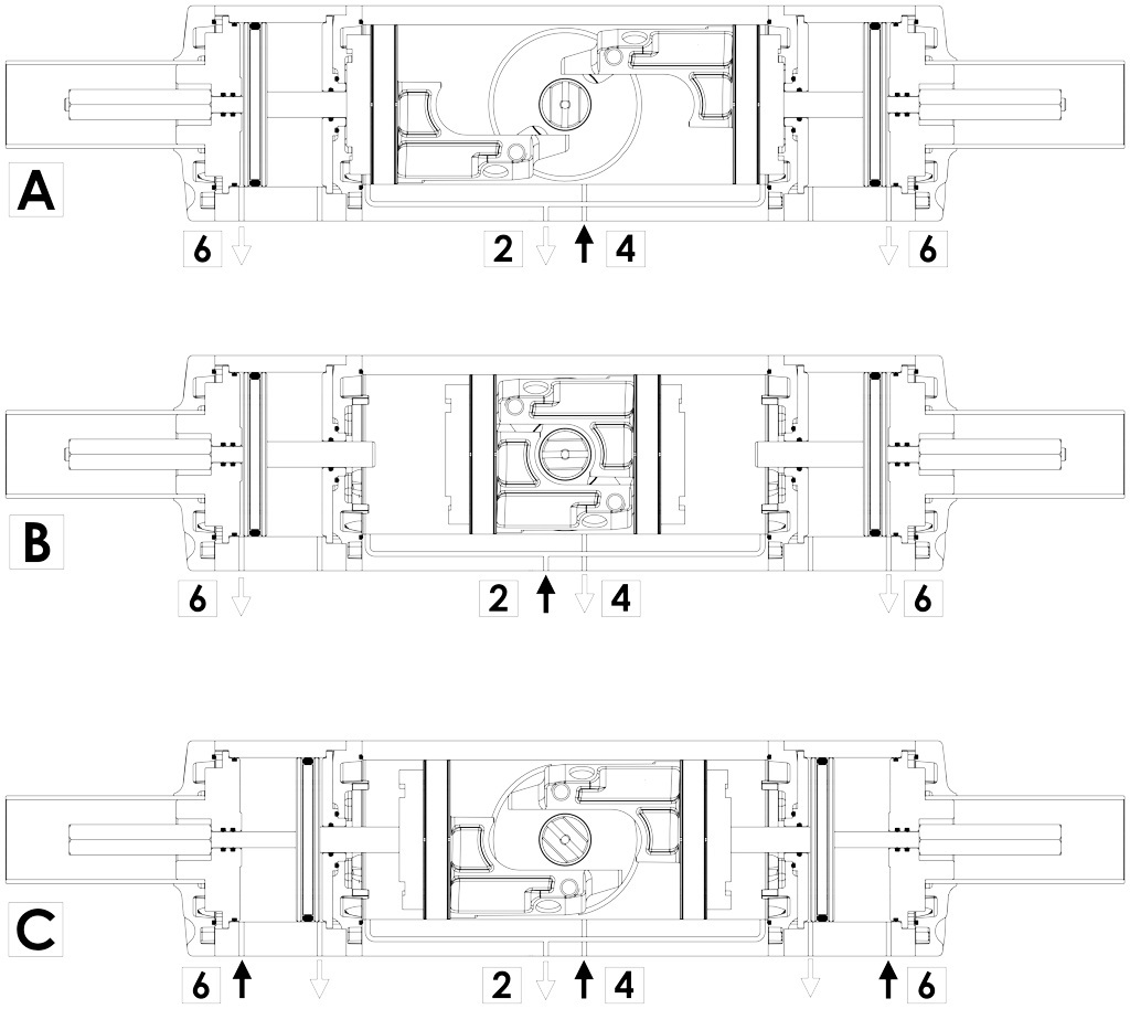
A. FULLY CLOSED POSITION In this position the air is supplied to port 4 with exhaust air at port 2 and 6.
B. FULLY OPEN POSITION (90° rough metering) In this position the air is supplied to port 2 with exhaust air at port 4 and 6.
C. INTERMEDIATE POSITION (fine metering) In this position the air is supplied to port 6 than to port 4, with exhaust air at port 2. In this case the external pistons will move to the desired rotating angle, consequently reducing the total valve flow.