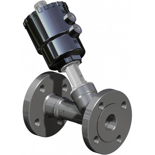
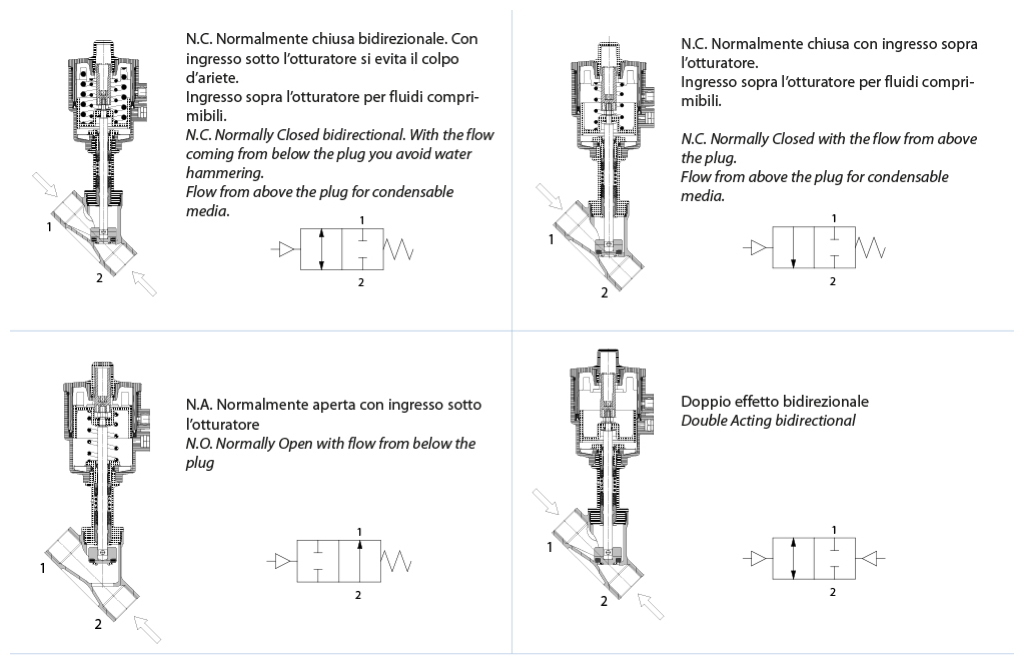
GENERAL FEATURES: Body valve material: A351-CF3M (316L S.S.). Valve ends: see code plan. Assembling is possible in all positions: upright, flat or angled. Range available from DN 15 to DN 50 in the Double Acting versions, Spring Return N.C. from above and below the plug, Spring Return N.O. from below the plug. The performance and the pressure’s diagrams are the same as per Standard versions but limited at PN16 On request: versions for vacuum and oxygen service 2014/34/EU ATEX configuration to request at time of order.
CONTROL MEDIA: Driving media: compressed air, lubricated or dry, gas or neutral media. Ambient temperature: -10°C to +60°C
OPERATING MEDIA: Air, water, alcohol, oil, petroleum products, saline solutions, steam, etc. (as long as compatible with CF3M (316L S.S.) or PTFE). Pressure from 0 to 16 bar (steam from 180°C, from 0 to 10 bar) depending on the size and model chosen see following pages. Temperature from –10°C to 180°C. Max. viscosity 600 cst (mm2/s).
Flanged UNI EN1092-1
ANSI 150RF FLANGED VALVE FACE TO FACE ASME B16.10 A1
DN [mm]
H
L
øN
øP
øQ
øR
F
15
11,3
9,7
35,1
89,0
60,5
16,0
108,0
20
12,8
11,2
42,9
99,0
69,8
16,0
117,0
25
15,0
13,4
50,8
108,0
79,2
16,0
127,0
32
15,8
14,2
63,5
117,0
88,9
16,0
140,0
40
18,0
16,4
73,0
127,0
98,6
16,0
165,0
50
19,1
17,5
91,9
152,0
120,6
19,0
178,0
REDUCED FLANGES VALVES
DN [mm]
H
øP
øQ
øR
F
15
7,0
70,0
50,0
7,0
104,5
20
8,0
75,0
55,0
9,0
119,5
25
9,0
80,0
60,0
9,0
134,5
32
9,0
90,0
70,0
9,0
149,5
40
10,0
100,0
80,0
9,0
164,5
50
10,0
110,0
90,0
11,0
179,5
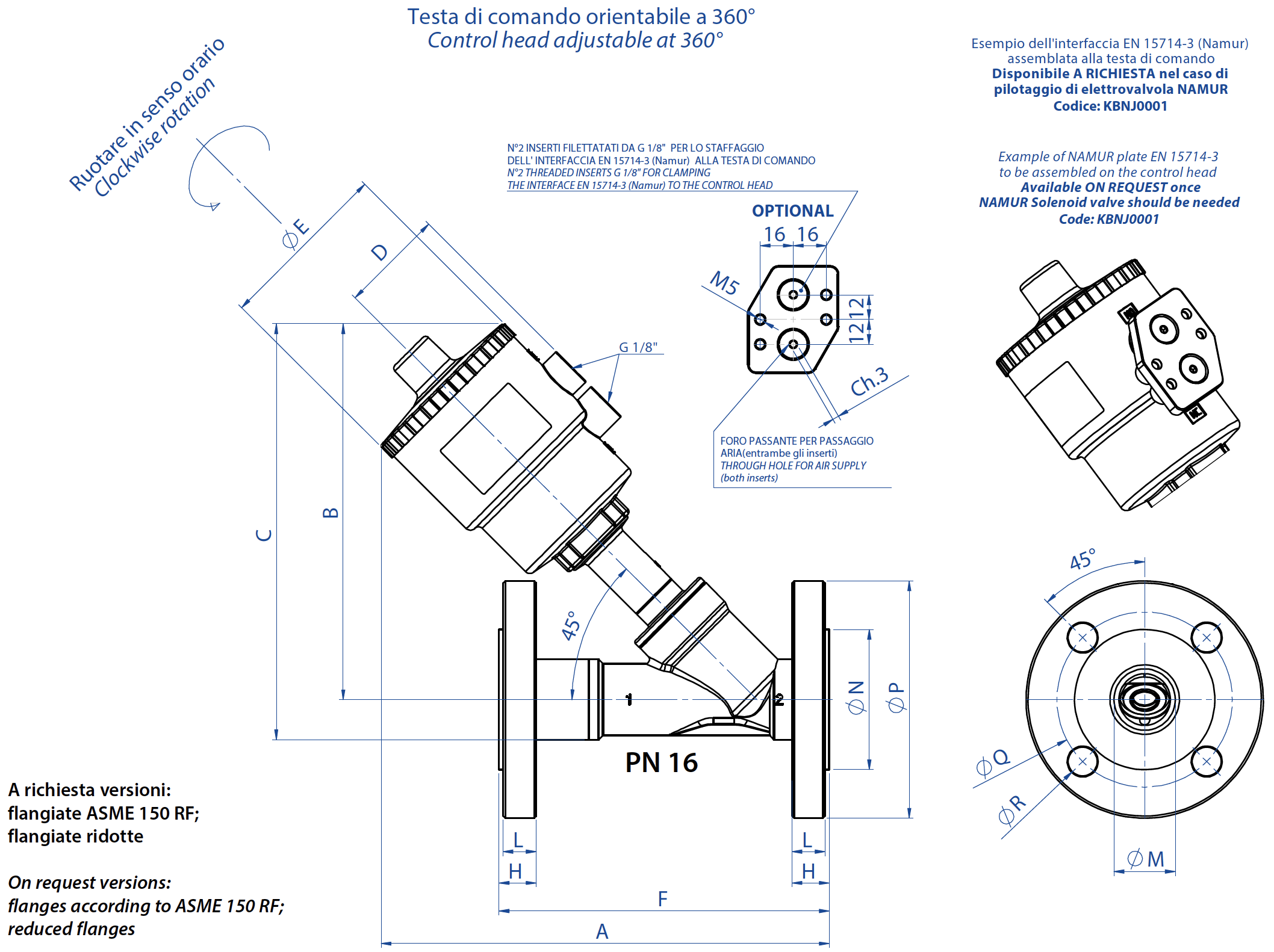
On request versions: flanges according to ASME 150 RF; reduced flanges
DIMENSIONS
DN [mm]
Control head
A
B
C
D
øE
F
H
L
øM
øN
øP
øQ
øR
15
ø 50
182,5
156
203,5
44
70
130
16
14
18,1
45
95
65
14
20
ø 50
192,3
160
212,5
44
70
150
18
16
23,7
58
105
75
14
20
ø 63
210,3
178
230,5
50,5
84,4
150
18
16
23,7
58
105
75
14
25
ø 50
197,36
164
221,5
44
70
160
18
16
29,7
68
115
85
14
25
ø 63
216,36
182
239,5
50,5
84,4
160
18
16
29,7
68
115
85
14
25
ø 90
256,36
222
279,5
66,2
116,4
160
18
16
29,7
68
115
85
14
32
ø 50
202,5
168
238
44
70
180
18
16
38,4
78
140
100
18
32
ø 63
220,5
186
256
50,5
84,4
180
18
16
38,4
78
140
100
18
32
ø 90
260,5
226
296
66,2
116,4
180
18
16
38,4
78
140
100
18
32
ø 110
296,5
261
331
77,4
140,6
180
18
16
38,4
78
140
100
18
40
ø 63
228,6
190
265
50,5
84,4
200
18
15
44,3
88
150
110
18
40
ø 90
268,6
230
305
66,2
116,4
200
18
15
44,3
88
150
110
18
40
ø 110
304,2
266
341
77,4
140,6
200
18
15
44,3
88
150
110
18
50
ø 63
241,87
200
282,5
50,5
84,4
230
18
15
55,7
102
165
125
18
50
ø 90
281,87
240
322,5
66,2
116,4
230
18
15
55,7
102
165
125
18
50
ø 110
317,87
276
358,5
77,4
140,6
230
18
15
55,7
102
165
125
18
Suggested executions are in bold. Other combinations on request.
METHODS OF USE
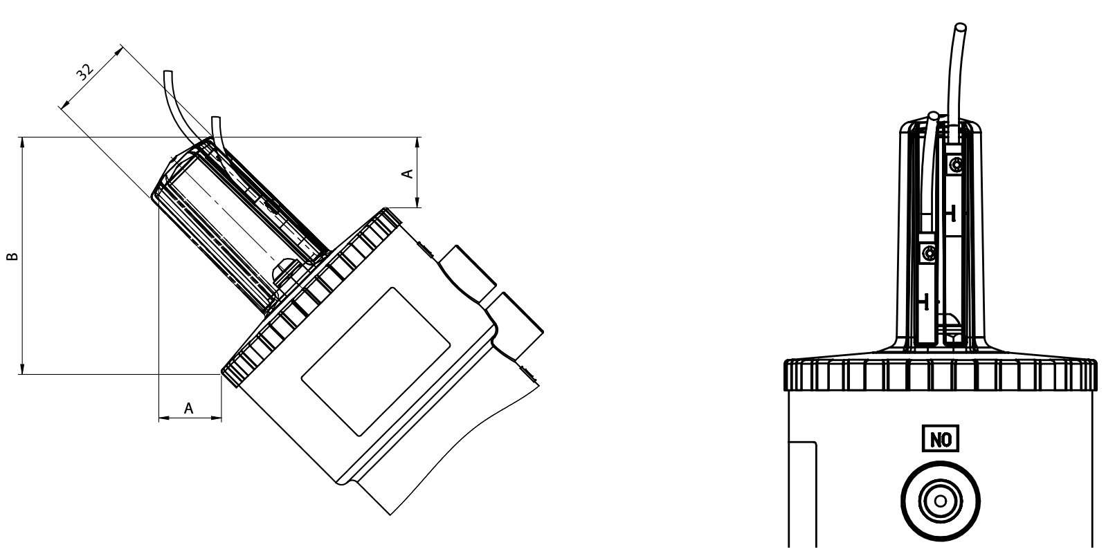
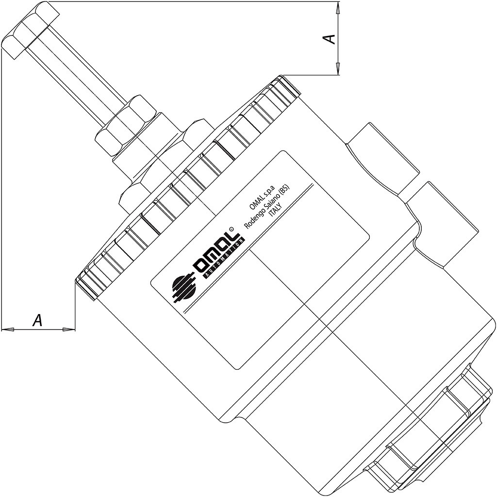
Limit switch cap
The special cap, made of transparent plastic material, has two grooves for fast attachment and adjustment of magnetic limit switches.The limit switches have an internal LED visible when the limit switch is energized.REED and HALL effect type limit switches are available with free connection or already wired M12.The cap has an IP68 protection rating.Attention: to enable proper fixing in the limit switch housing, the visual indicator, when the valve is fully open, does not reach the end of the plug. The limitswitches must be set once the valve is installed in the system.
Kit code
Head size
A mm
B mm
KFJM16
∅ 50
30
77
KFJM18
∅ 63
26
87
KFJM21
∅ 90
15
97
KFJM23
∅ 110
8
107
Kit does not include limit switches.
Stroke limiter It allows to limit the plug run in opening phase, therefore it regulates the flow. Available on all versions. In spring return normally open version it can be used as an emergency control.
Control
A mm
Code
∅ 50
25,5
KLJL0016
∅ 63
21,5
KLJL0018
∅ 90
5,2
KLJL0021
∅ 110
5,9
KLJL0023
Not available with ∅ 40 head.
Emergency manual override It allows to open the valve in emergency cases (lack of pilot fluid, machinery damaged, lack of piloting signal). It is available on all normally closed valves.
Control
A mm
Code
∅ 50
35,8
KLJA0016
∅ 63
35,8
KLJA0018
∅ 90
29,5
KLJA0021
∅ 110
29,5
KLJA0023
Not available with ∅ 40 head
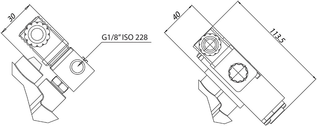
Electro-pilot 3/2 - Solenoid valve 3/2 - 5/2
Control solenoid valve Electro-pilot 3/2 for direct assembling. Body and reel positionable at 360°. Standard manual control. Solenoid valve (NAMUR) sets for selection between function 5/2 or 3/2, achievable by mounting the corresponding plate (both supplied). Room temperature: from –10°c to +50°C.
Voltage
24 Vac
115 Vac
230 Vac
24 Vdc
Electro-pilot
EP415024
EP415110
EP415220
EP412024
Voltage
24 Vac
115 Vac
230 Vac
24 Vdc
NAMUR Solenoid valve*
ER8188A2
ER8188A4
ER8188A5
ER8188C2
NAMUR interface
KBNJ0001 Not available with ∅ 40 head
* To be usedy with NAMUR interface only
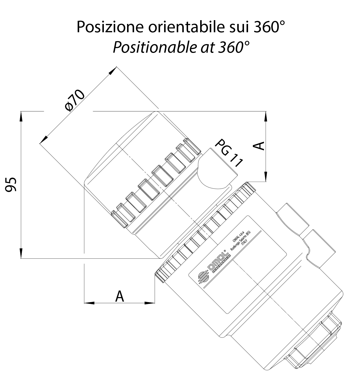
Limit switch box The control box to check the open/close positions with two mechanical limit switches is suitable for assembling on all the range of valves with actuators ∅50 - ∅63 - ∅90 - ∅110. The terminals to connect the solenoid valve and the visual indicators provided with led are optional. Level of protection: IP 65. Room temperature: from –20° C to +70°C. Access lead nr. 1 PG11. Body material: polyamide (cap in trasparent polymethacrylate).
Control
A mm
∅ 50
52,1
∅ 63
47,5
∅ 90
37,7
∅ 110
29,5
AVAILABLE LIMIT SWITCH
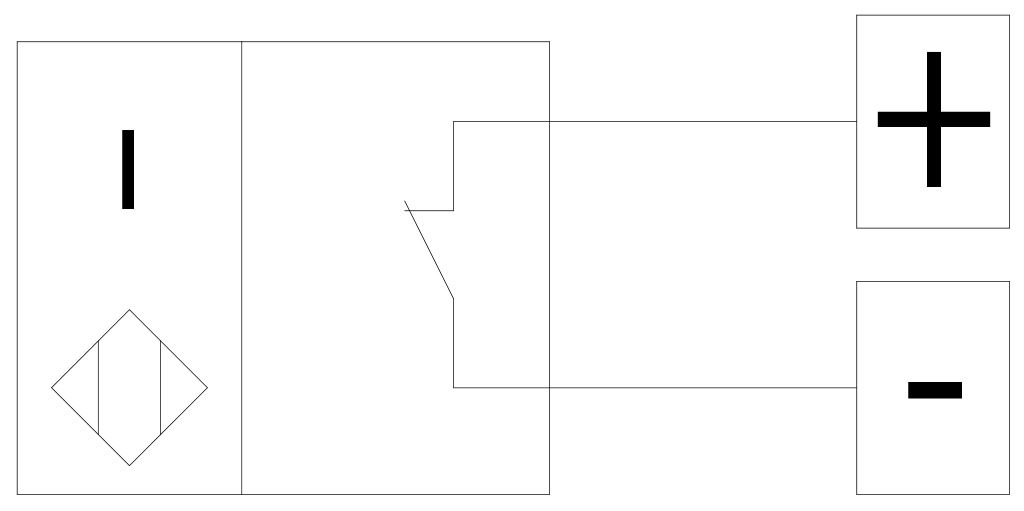
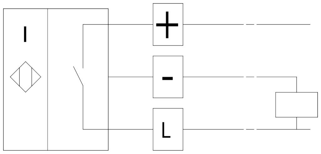
Inductive limit switches NAMUR EExia Nominal voltage: 8 Vdc Consumes: working ≤1mA; resting ≥3 mA Working temperature: from –20°C to +70°C
Configuration
Code
1 Limit switch at the top: open valve
KSIN9A0xx
1 Limit switch at the bottom: close valve.
KSIN9C0xx
2 Limit switch open and close valve
KSIN920xx
Proximity limit switches Nominal voltage: 10÷30 Vdc Consumes: 15mA; Working temperature: from –20°C to +70°C
Configuration
Code
1 Limit switch at the top: open valve
KSI09A0xx
1 Limit switch at the bottom: close valve.
KSI09C0xx
2 Limit switch open and close valve
KSI0920xx
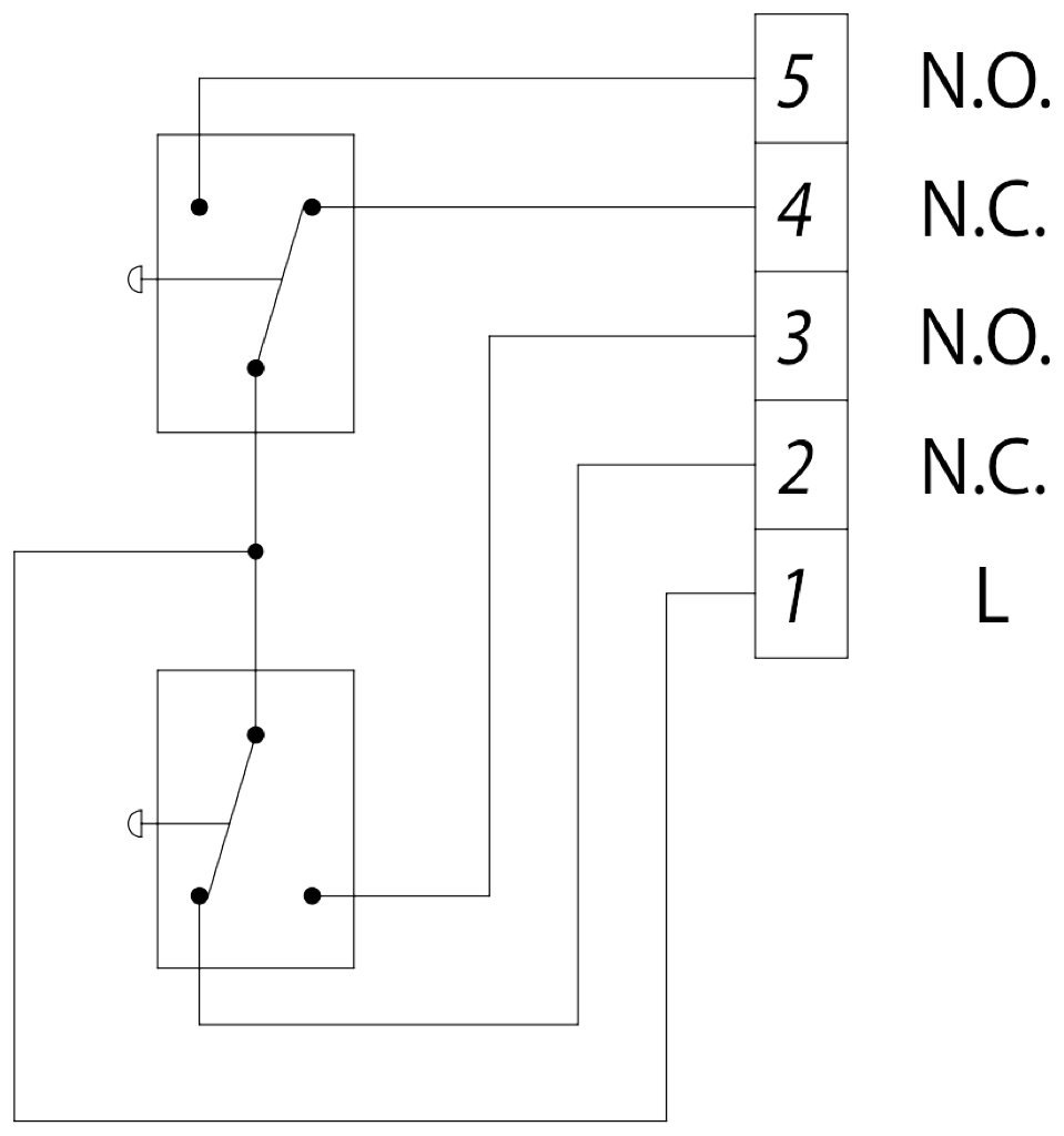
Mechanical limit switches Limit switch at the top: open valve Limit switch at the bottom: close valve Max. capacity: 5A 250 Vac; 1A 250 Vdc
Configuration
Code
2 Limit switch
KSM0C20xx
xx = Ø control heads 16 = Ø50 18 = Ø63 21 = Ø90 23 = Ø110