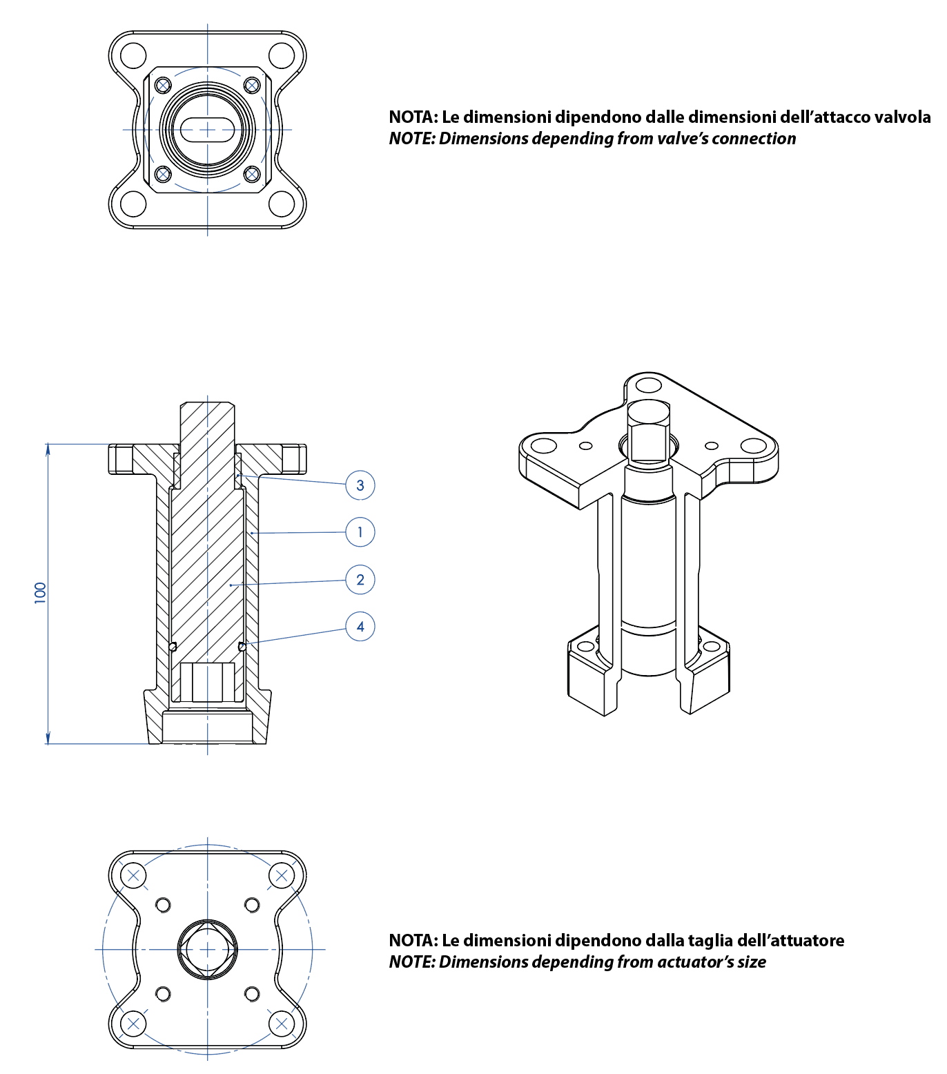
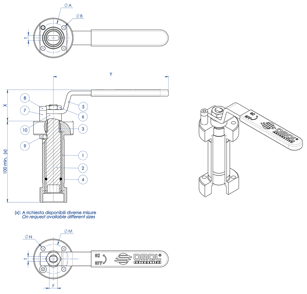
1. Antistatic device ((electrical continuity between ball, stem and body) Static electricity is avoided which can cause sparks and fire in an inflammable/explosive environment Contact safety throughout the entire life of the valve
2. Double antifriction washer Less Breakaway Torque is granted Less wear comparing with the execution with the single washer
3."V" seals pack; 3 seals + o-ring It ensures a perfect tightness even after a high number of cycles
4. Spring washer on the shaft seal Guarantee of the recovery of the gap due to the wear caused by the rotational movement of the shaft avoiding leakage towards the outside part. Allow to maintain energized the "chevron" seals (V), thus avoiding any leakage to the outside, against huge temperature excursions
5. Stretch Graphite seal Tightness towards outside is granted, independently by the thermal excursions to which the valve is subjected
Greater precision in the alignment of axes due to a unique positioning in the process machining from raw material to finished valve Longer lifetime of the valve Less breakaway torque
Valve body in carbon steel made with NACE certified material as standard Greater corrosion resistance Greater ductility of the material
100% in- house manufacturing process technology Maximum control and accuracy in all the stages of the manufacturing process Flexibility in supply quickly special executions requested by customers
"Fire safe" Certificate Guarantees the tightness of the valve also in case of fire
ATEX Certificate Installation is possible in a potential explosive environment
TA LUFT fugitive emission Certificate High level of safety of the tightness towards the outside is granted
PED Certificate Full compliance with European Safety Standards for Pressure Equipment
UP to SIL 3 certified Guarantee of the high level of functional safety
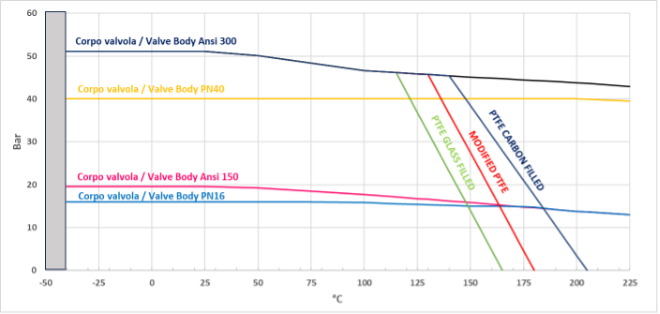
STANDARD FEATURES • No protuding floating ball, full bore • Soft-seat seal Modified PTFE • Standard for connecting flanges: EN 1092-1 ed. 2008; ASME B16.5 • Operating temperature see temperature pressure diagram • Pressure class: PN16-40 - ANSI 150-300 • Tightness Class: EN12266-1 rate A • Intercepted fluid: air, water, gas, petroleum and petrochemical products, aggressive fluids • Antistatic device EN12266-2 • Stem seal: Modified PTFE V-pack • Additional seal on stem with FKM O-ring • Anti Blow-out stem • Actuator connection as per standard ISO 5211 • Closing angle >7°
FEATURES ON REQUEST • For other flange types please contact our sales department. • Sealing in: PTFE reinforced with glass (PTFE-GF), PTFE reinforced with carbongraphite (PTFE-CF). For other types of materials please contact our sales department • Mono-directional version with pressure-relief hole in the ball • Stainless steel lever • Stainless steel Stem nuts and springs • For versions in materials different from the standard (body, ball, stem), please contact our sales department. • ATEX marking and certificate ON REQUEST CERTIFICATIONS • In compliance with European Directive 2014/68/EU PED; Fugitive Emission ISO 15848 (ISO FE BH-C03-SSA 0); TA-LUFT VDI 2440; FIRE SAFE: ISO 10497 Third ed. 2010 / API 607 Sixth ed. 2010 • Safety integrity level up to SIL3 according to the IEC 61508 • In compliance with ATEX 2014/34/EU Directive , ATEX certificate ON REQUEST. ENGINEERING STANDARDS • Body thickness in compliance with: ASME B16.34, ASME VIII div.1, EN 12516. • Materials and rating in compliance with ASME B16.34 for ANSI valves and EN 12516 for PN valves
DIMENSIONS
SIZE
∅E
L
B
C
ATT.ISO
∅M
∅N
F/T
H
Y
∅V
LEVER KIT
DN [mm]
[inch]
DN 15
1/2"
13
53
52
10
F03
36
M5
10/6
71
140
---
KLV58004
DN 20
3/4"
19
53
55
10
F03
36
M5
10/6
73
140
---
KLV58004
DN 25
1"
25
58
68
15
F04
42
M5
12/8
87
150
---
KLV58006
DN 32
1" 1/4
32
65
73
15
F04
42
M5
12/8
91
150
---
KLV58006
DN 40
1" 1/2
38
79
93
21
F05
50
M6
16/10
108
275
---
KLV58008
DN 50
2"
51
90
102
21
F05
50
M6
16/10
118
275
---
KLV58008
DN 65
2" 1/2
64
107
130,5
28
F07
70
M8
22/14
143
350
---
KLV58010
DN 80
3"
76
120
137,5
28
F07
70
M8
22/14
150
350
---
KLV58010
DN 100
4"
102
167
172
35
F10
102
M10
30/18
198
450
---
KLV58012
DN 125
5"
118
180
182
35
F10
102
M10
30/18
208
450
---
KLV58012
DN 150 PN16-ANSI150 (*)
6"
152
240
227,5
40,5
F14
140
M16
45/30
522
326
400
---
DN 150 PN25-40 - ANSI300
6"
152
240
227,5
40,5
F14
140
M16
45/30
522
347,5
600
---
DN 200 PN16-PN25-ANSI150 (*)
8"
203
314
274
44,8
F14
140
M16
52/35
516
347
500
---
DN 200 PN40
8"
203
314
274
44,8
F14
140
M16
52/35
614
348
500
---
STANDARD version with manual gearbox for DN150 and DN200. (*) ON REQUEST version with manual lever.
DIMENSIONS -PN-
SIZE
PN
A
∅G
∅R
S
∅H
HOLES N°
∅I
P
Kg
L
SEALS KIT
DN [mm]
[inch]
DN 15
1/2"
PN 16-40
32
90
45
2
65
4
M12
15
2,1
53
KGBV485040
DN 20
3/4"
PN 16-40
35
100
58
2
75
4
M12
14
2,4
53
KGBV485050
DN 25
1"
PN 16-40
42
110
68
2
85
4
M12
16
3,5
58
KGBV485060
DN 32
1" 1/4
PN 16-40
47
130
78
2
100
4
M16
20
5,2
65
KGBV485070
DN 40
1" 1/2
PN 16-40
58
140
88
3
110
4
M16
20
7,5
79
KGBV485080
DN 50
2"
PN 16-40
67
150
102
3
125
4
M16
20
9,7
90
KGBV485090
DN 65
2" 1/2
PN 16
83
178
122
3
145
4
M16
20
16,4
107
KGBV485100
DN 65
2" 1/2
PN 25-40
83
178
122
3
145
8
M16
20
16,1
107
KGBV485100
DN 80
3"
PN 16-40
90
190
138
3
160
8
M16
20
20,2
120
KGBV485110
DN 100
4"
PN 16
107
235
158
3
180
8
M16
20
40,4
167
KGBV485120
DN 100
4"
PN 25-40
107
235
162
3
190
8
M20
25
40,5
167
KGBV485120
DN 125
5"
PN 16
117
250
188
3
210
8
M16
25
48,2
180
KGBV485130
DN 125
5"
PN 25-40
125
270
188
3
220
8
M24
30
57,9
180
KGBV485130
DN 150(*)
6"
PN 16
154
332
212
3
240
8
M20
25
109,3
240
KGBV485140
DN 150
6"
PN 25-40
154
332
218
3
250
8
M24
24
111,5
240
KGBV48514D
DN 200(*)
8"
PN 16
188
396
268
3
295
12
M20
30
191,8
314
KGBV485150
DN 200(*)
8"
PN 25
188
396
278
3
310
12
M24
30
196,5
314
KGBV485150
DN 200
8"
PN 40
195
408
285
3
320
12
M27
30
220
314
KGBV48515D
DIMENSIONS -ANSI-
SIZE
ANSI
A
∅G
∅R
S
∅H
HOLES N°
∅I
P
Kg
L
SEALS KIT
DN [mm]
[inch]
DN 15
1/2"
ANSI 150
32
90
35,1
1,6
60,5
4
1/2”UNC
16
2,1
53
KGBV485040
DN 15
1/2"
ANSI 300
34
90
35,1
1,6
66,5
4
1/2”UNC
16
2,1
53
KGBV485040
DN 20
3/4"
ANSI 150
35
100
42,9
1,6
69,8
4
1/2”UNC
16
2,5
53
KGBV485050
DN 20
3/4"
ANSI 300
40
110
42,9
1,6
82,6
4
5/8”UNC
16
3,1
53
KGBV485050
DN 25
1"
ANSI 150
42
110
50,8
1,6
79,2
4
1/2”UNC
16
3,4
58
KGBV485060
DN 25
1"
ANSI 300
45
118
50,8
1,6
88,9
4
5/8”UNC
20
3,8
58
KGBV485060
DN 32
1" 1/4
ANSI 150
47
130
63,5
1,6
89
4
1/2”UNC
20
5,2
65
KGBV485070
DN 32
1" 1/4
ANSI 300
47
130
63,5
1,6
98,6
4
5/8”UNC
20
5,2
65
KGBV485070
DN 40
1" 1/2
ANSI 150
58
140
73
1,6
98,6
4
1/2”UNC
20
7,5
79
KGBV485080
DN 40
1" 1/2
ANSI 300
58
150
73
1,6
114,3
4
3/4”UNC
22
8,6
79
KGBV485080
DN 50
2"
ANSI 150
67
150
91,9
1,6
120,6
4
5/8”UNC
20
9,7
90
KGBV485090
DN 50
2"
ANSI 300
73
160
91,9
1,6
127,0
8
5/8”UNC
20
11,2
90
KGBV485090
DN 65
2" 1/2
ANSI 150
83
178
104,6
1,6
139,7
4
5/8”UNC
20
16,5
107
KGBV485100
DN 65
2" 1/2
ANSI 300
89
190
104,6
1,6
149,4
8
3/4”UNC
25
18,7
107
KGBV485100
DN 80
3"
ANSI 150
90
190
127
1,6
152,4
4
5/8”UNC
20
20,7
120
KGBV485110
DN 80
3"
ANSI 300
96
205
127
1,6
168,1
8
3/4”UNC
25
24,0
120
KGBV485110
DN 100
4"
ANSI 150
107
235
157,2
1,6
190,5
8
5/8”UNC
20
40,7
167
KGBV485120
DN 100
4"
ANSI 300
115
250
157,2
1,6
200,2
8
3/4”UNC
25
48,2
167
KGBV485120
DN 125
5"
ANSI 150
117
250
185,7
1,6
215,9
8
3/4”UNC
30
48,3
180
KGBV485130
DN 150(*)
6"
ANSI 150
154
332
215,9
1,6
241,3
8
3/4”UNC
25
110,3
240
KGBV485140
DN 150
6"
ANSI 300
154
332
215,9
1,6
269,7
12
3/4"UNC
25
112
240
KGBV48514D
DN 200(*)
8"
ANSI 150
188
396
269,7
1,6
298,4
8
3/4”UNC
30
193,7
314
KGBV485150
STANDARD version with manual gearbox for DN150 and DN200. (*) ON REQUEST version with manual lever.