Cast iron butterfly valve for mounting between flanges, “Lug” type
ITEM 385
Body: Cast iron
Butterfly: Cast iron
Liner: see table
ITEM 386
Body: Cast iron
Butterfly: AISI 316
Liner: see table
ITEM 387
Body: Cast iron
Butterfly: Bronze aluminium
Liner: see table
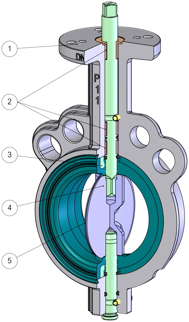
1. EN ISO 5211 top mounting
Easy coupling with every kind of drives.
2. Three guiding bushings on the shaft
It grants a perfect alignment of the shaft on the body and prevents oscillations even with high pressure.
Less friction between the shaft and body.
3. Vulcanized liner on rigid ring
Less deformation of the liner
Easy assembly / disassembly of the liner for maintenance
No deformation of the liner between the flanges during assembly
Greater dimensional accuracy during the injection/molding
4. Shaft in 2 pieces without fixing components
Easy assembly / disassembly of the disc for maintenance
Higher Kv thanks to the central section of the disk thinner than a valve with a single shaft
5. Lapped surface of the disc's circumference
Better tightness and less wear of the liner
Lower torque due to less friction between the disc and liner
Wide range of LINER materials
Various applications possibility
ATEX Certificate
Installation is allowed in a potential explosive environment
PED Certificate
Full compliance with European Safety Standards for Pressure Equipment
GENERAL FEATURES:
OMAL butterfly valves, available in wafer or lug version from DN 40 to DN 600 (lug DN 300), are designed and manufactured to be used in most applications in all industrial fields.
STANDARD EXECUTIONS:
• Available range: from DN 40 to DN 300 PN 10 - PN 16.
• Standard flanges: PN 10=PN 16 - from DN 40 to DN 150; PN 10 or PN 16 from DN 200 to DN 300.
• On request PN 16 from DN 200 to DN 300.
• General requirements in accordance with UNI EN593.
• Face to face as per EN 558 serie 20.
• Valve head as per ISO 5211.
• Tightness as per EN 12266-1 rate A.
• Other tests on request.
• Operating temperature of liners:
EPDM: from -25°C to +135°C;
NBR: from -23°C to +82°C;
FKM: from -10°C to +190°C;
PTFE (on EPDM core): from -25°C to +135°C.
• Working pressure between flanges: PN 16 bar for DN 40 to DN 150; PN 10 or PN 16 bar
ON REQUEST:
• Working temperature for special liners:
SILICONE: from -25°C to +160°C;
NBR CARBOX: from -10°C to +82°C;
NBR WHITE for food: from -23°C to +82°C;
HNBR: from -20°C to +120°C.
• For other applications, please contact our sales department.
CERTIFICATIONS:
• According to 2014/68/EU “PED”.
• DVGW homologation for gas (V386).
• RINA homologation.
• Conformity to the italian D.M.n°174 suitable with drinking water and alimentary fluid (V386).
• ATEX version in conformity with European Directive 2014/34/EU.
• ATEX certificate on request (For valves with PTFE liner, up to DN 200 only).
DIMENSIONS | ||||||||||||||||||
| SIZE | PN | A | B | ØC | ØD | ØE | ØF | □G | ØI | P | Q | R | S | ØT | U | ØZ | Holes | |
| DN [mm] | [inch] | |||||||||||||||||
| DN 40 | 1"1/2 | 10-16 | 33 | 36 | 50 | 70 | 6,5 | 8,5 | 9 | 110 | 70 | 125 | 31 | 9 | 14,2 | 118 | M16 | 4 |
| DN 50 | 2" | 10-16 | 43 | 46 | 50 | 70 | 6,5 | 8,5 | 9 | 125 | 80 | 140 | 31 | 9 | 14,2 | 125 | M16 | 4 |
| DN 65 | 2"1/2 | 10-16 | 46 | 49 | 50 | 70 | 6,5 | 8,5 | 11 | 145 | 86 | 152 | 33 | 11 | 14,2 | 139 | M16 | 4 |
| DN 80 | 3" | 10-16 | 46 | 49 | 50 | 70 | 6,5 | 8,5 | 11 | 160 | 95,5 | 159 | 33 | 11 | 14,2 | 184 | M16 | 8 |
| DN 100 | 4" | 10-16 | 52 | 56 | 50 | 70 | 6,5 | 8,5 | 11 | 180 | 108 | 178 | 33 | 11 | 14,2 | 204 | M16 | 8 |
| DN 125 | 5" | 10-16 | 56 | 59 | 70 | 8,5 | 14 | 210 | 124,5 | 190,5 | 36 | 14 | 19 | 230 | M16 | 8 | ||
| DN 150 | 6" | 10-16 | 56 | 59 | 70 | 8,5 | 14 | 240 | 137 | 203 | 36 | 14 | 19 | 266 | M20 | 8 | ||
| DN 200 | 8" | 10 | 60 | 64 | 70 | 8,5 | 17 | 295 | 166 | 238 | 39 | 17 | 22,2 | 318 | M20 | 8 | ||
| DN 250 | 10" | 10 | 68 | 72 | 102 | 125 | 11 | 13 | 17 | 350 | 199 | 268 | 50 | 17 | 28,5 | 395 | M20 | 12 |
| DN 300 | 12" | 10 | 78 | 81,5 | 102 | 125 | 11 | 13 | 22 | 400 | 234 | 306 | 55 | 22 | 28,5 | 448 | M20 | 12 |
| DN 200 | 8" | 16 | 60 | 64 | 70 | 8,5 | 17 | 295 | 166 | 238 | 39 | 17 | 22,2 | 329 | M20 | 12 | ||
| DN 250 | 10" | 16 | 68 | 72 | 102 | 125 | 11 | 13 | 22 | 355 | 199 | 268 | 55 | 22 | 28,5 | 395 | M24 | 12 |
| DN 300 | 12" | 16 | 78 | 81,5 | 102 | 125 | 11 | 13 | 22 | 410 | 234 | 306 | 55 | 22 | 28,5 | 448 | M24 | 12 |
LEVER FEATURES
10-position lever; lockable in each position
Material: Aluminium;
Surface coating: polyester
Weight: from 0,3 to 0,9 Kg.
DIMENSIONS | ||||||
| SIZE | A | B | øC | D | Kg | |
| DN [mm] | [inch] | |||||
| DN 40 | 1" 1/2 | 188 | 70 | 90 | 160 | 2,5 |
| DN 50 | 2" | 203 | 80 | 90 | 160 | 3,4 |
| DN 65 | 2" 1/2 | 225 | 86 | 90 | 220 | 4,3 |
| DN 80 | 3" | 230 | 95,5 | 90 | 220 | 5,5 |
| DN 100 | 4" | 250 | 108 | 90 | 220 | 6,6 |
| DN 125 | 5" | 277 | 124,5 | 90 | 350 | 9 |
| DN 150 | 6" | 290 | 137 | 90 | 350 | 11,4 |
| DN 200 | 8" | 325 | 166 | 90 | 350 | 17,5 |
GEAR BOX FEATURES
Designed tested mechanism, working through pinion and worm.
Visual indicator gives the position of the valve
Aluminium alloy carter for the gear box “RF0 " type, cast iron for the gear box “RRM..." Type
Cast iron pinion.
Worm gear in hardened steel.
Steel wheel.
Epoxy painted external surface.
DIMENSIONS | ||||||||||||||
SIZE | PN | A | B | C | D | ØE | F | G | H | I | L | M | Kg | |
| DN [mm] | [inch] | |||||||||||||
| DN 40 | 1"1/2 | 10-16 | 200 | 49 | 24 | 80 | 140 | 115 | 42 | 35 | 171,2 | 70 | 160 | 3,6 |
| DN 50 | 2" | 10-16 | 200 | 49 | 24 | 80 | 140 | 115 | 42 | 35 | 185,9 | 80 | 160 | 4,5 |
| DN 65 | 2"1/2 | 10-16 | 200 | 54 | 27 | 100 | 200 | 130 | 50 | 40 | 201,6 | 86 | 150 | 5,9 |
| DN 80 | 3" | 10-16 | 200 | 54 | 27 | 100 | 200 | 130 | 50 | 40 | 208 | 95,5 | 150 | 7,1 |
| DN 100 | 4" | 10-16 | 200 | 54 | 27 | 100 | 200 | 130 | 50 | 40 | 227 | 108 | 150 | 8,2 |
| DN 125 | 5" | 10-16 | 200 | 54 | 27 | 100 | 200 | 130 | 50 | 40 | 239,7 | 124,5 | 150 | 10,2 |
| DN 150 | 6" | 10-16 | 200 | 54 | 27 | 100 | 200 | 130 | 50 | 40 | 252,4 | 137 | 150 | 12 |
| DN 200 | 8" | 10 | 250 | 70,5 | 40,5 | 140 | 300 | 175 | 60 | 60 | 300,7 | 166 | 180 | 21,6 |
| DN 250 | 10" | 10 | 250 | 70,5 | 40,5 | 140 | 300 | 175 | 60 | 60 | 342 | 199 | 180 | 29,8 |
| DN 300 | 12" | 10 | 250 | 70,5 | 40,5 | 140 | 300 | 175 | 60 | 60 | 380 | 234 | 180 | 45,1 |
| DN 200 | 8" | 16 | 250 | 70,5 | 40,5 | 140 | 300 | 175 | 60 | 60 | 300,7 | 166 | 180 | 21,6 |
| DN 250 | 10" | 16 | 250 | 70,5 | 40,5 | 140 | 300 | 175 | 60 | 60 | 342 | 199 | 180 | 29,8 |
| DN 300 | 12" | 16 | 250 | 70,5 | 40,5 | 140 | 300 | 175 | 60 | 60 | 380 | 234 | 180 | 45,1 |
MATERIALS | ||
| 1 | Body | A536 65-45-12 (GGG50) (Equivalent to EN-GJS-450-10 EN-JS 1040) |
| 2 | Disc | A536 65-45-12 (GGG50) - A351 CF8M (316 S.S.) |
| 3* | Liner | EPDM-NBR |
| 4 | Upper shaft | A276 S42000 (420 S.S.) (Equivalent to X20CR13; 1.4021) |
| 5 | Lower shaft | A276 S42000 (420 S.S.) (Equivalent to X20CR13; 1.4021) |
| 6* | Lower O-ring | EPDM-NBR (a with part. 3 in FKM) |
| 7* | Upper bush | Epoxy resin |
| 8* | Shaft bush | Epoxy resin with PTFE from DN40 to DN300, Bronze from DN350 to DN600 |
| 9* | Elastic pin | Stainless steel |
| 10* | Shaft O-ring | EPDM-NBR |
BODY
DN40 - 600
CAST IRON A536 65-45-12 *
EPOXY COATED
RAL 5015*
STEM
STAINLESS STEEL A276 S4200 *
STAINLESS STEEL A564 TP 630
DISC
DN40 - 600
CAST IRON A536 65-45-12*
CHEMICAL NICKEL PLATING
STAINLESS STEEL A351-CF8M (316 S.S.)*
STAINLESS STEEL A351-CF3M (316 S.S.) POLISHED
BRONZE/ALUMINIUM B148C95400 *
*Standard OMAL supply
LINER
DN40 - 600
EPDM*
NBR*
DN40 - 300
FKM*
PTFE ON EPDM*
WHITE NBR
POTABLE WATER WHITE NBR
HNBR
CARBOX NBR
SILICONE
MATERIAL APPLICATIONS | ||
MATERIAL | FEATURES | APPLICATIONS |
| CAST IRON A536 65-45-12 | Mechanical strength as good as stainless steel | General applications Used as a standard for body and disc |
| BRONZE - ALUMINIUM | Good corrosion resistance | Corrosive fluids, sea water |
| RILSAN COATED | Excellent corrosion resistance | General applications Used as a standard for body and disc |
| STAINLESS STEEL A351-CF8M | Excellent corrosion resistance | Food, chemical, pharmaceutical...etc |
| EPDM | Temperature limits (°C): -50°/+150°. Operating temperature (°C): -40°/+135. Unsuitable for hydrocarbons. | Water (soft, sea, glycolic and industrial), steam, ozone, bases and diluted acids, acetic solvents, alcohol, caustic soda, atmospheric agents. |
| NBR | Good abrasion/wear resistance. Good chemical and mechanical srenght to mineral oils, some hydrocarbons and aliphatic solvents. Operating temperature (°C): -23 / + 82. Unsuitable for acetone, ketones, nitrates and chlorinated hydrocar- bons. | General applications, compressed air, cold water, hydraulic fluids, methane, butane, petroleum, sea water, abrasive materials for pneumatic circuits, animal and vegetables fats. |
| WHITE NBR | Good abrasion/wear resistance. Good chemical and mechanical srenght to mineral oils, some hydrocarbons and aliphatic solvents. Operating temperature (°C): -23 / + 82. Unsuitable for acetone, ketones, nitrates and chlorinated hydrocar- bons. | General applications, compressed air, cold water, hydraulic fluids, methane, butane, petroleum, sea water and abrasive materials for pneumatic circuits. |
| POTABLE WATER WHITE NBR | Suitable for potable water accordingly to italian law D.L. 174/2004. Operating temperature (°C): -23 / + 82. Unsuitable for acetone, ketones, nitrates and chlorinated hydrocar- bons. | General applications, compressed air, cold drinking water, hydraulic fluids, methane, butane, petroleum, sea water and abrasive materials for pneumatic circuits. |
| CARBOX NBR | Good abrasion/wear resistance. Good chemical and mechanical srenght to mineral oils, some hydrocarbons and aliphatic solvents. Operating temperature (°C): -10 / + 82. Unsuitable for acetone, ketones, nitrates and chlorinated hydrocar- bons. | Abrasive dusts and fluids |
| HNBR | Good abrasion/wear resistance. Good chemical and mechanical srenght to mineral oils, some hydrocarbons and aliphatic solvents. Operating temperature (°C): -20 / +120. Unsuitable for acetone, ketones, nitrates and chlorinated hydrocar- bons. | General applications, compressed air, cold water, hydraulic fluids, methane, butane, petroleum, sea water and abrasive materials for pneumatic circuits. |
| FKM | Excellent chemical and mechanical strenght to heat, atmospheric agents, benzoic solvents. Gas-proof. Unsuitable for steam and boi- ling water. Operating temperature (°C): -10 / +190. | Solvents (acetic excluded), solid hydrocarbons, oxygenating fuels, acids, bases, hydraulic fluids, oils. |
| HIGH TEMPERATURE SILICONE | Excellent chemical and mechanical strenght to steam and superhheated water (150°C). Operating temperature (°C): -25 / +160. | Air or hot inert gas (Temperature limits (°C): +180), food industry, water, steam. |
| PTFE ON EPDM | Excellent chemical strenght to solvents and corrosive products. Unsuitable for abrasive fluids, alkaline metals ( potassium, sodium), gaseous fluorine. Operating temperature (°C): -25 / +135. | Very corrosive products for chemical industry and food industry. |
| NOTE: The table above lists typical features and applications of all “OMAL” products. Nevertheless, if unusual situations occur (i.e. special applications, contacts with particular fluids, extraordinary pressure or temperature conditions, ...) the elements which determine corrosion and abrasion might change and, as a consequence, metal performances might change, too. It is always the customer who has to choose the right material; however, our technical department is willing to meet all customers requests. | ||
BREAKAWAY TORQUES Nm | ||||||||||
| SIZE | DN 40 1"1/2 | DN 50 2" | DN 65 2"1/2 | DN 80 3" | DN 100 4" | DN 125 5" | DN 150 6" | DN 200 8" | DN 250 10" | DN 300 12" |
| PN 10 bar | 15 | 15 | 17 | 19 | 27 | 36 | 54 | 109 | 145 | 218 |
| PN 16 bar | 18 | 18 | 25 | 27 | 35 | 52 | 72 | 142 | 170 | 250 |
After inserting the valve between the flanges, but before screwing the bolts up, the butterfly must be switched into the “open” position. Otherwise, you might damage or permanently deform the sealing, while closing the valve.
Example of wrong mounting: the flanges are not open enough and the sealing might be damaged.
OMAL butterfly valves are assembled between pipe flanges without other rings and they are centered by means of tie-rods and fixing screws. Their diameter must conform to the following values.
D0 minimum flange diameter necessary for the inspection of the valve (with a perfectly centered valve)
D1 maximum flange diameter which allows the best possible uses
D2 maximum flange diameter which allows uses at low pressure. If you need any other information, please contact our technical department.
FLANGE SIZE | |||||||||||||||
| Diameter | DN 40 | DN 50 | DN 65 | DN 80 | DN 100 | DN 125 | DN 150 | DN 200 | DN 250 | DN 300 | DN 350 | DN 400 | DN 450 | DN 500 | DN 600 |
| D0 [mm] | 30 | 36 | 51 | 67 | 93 | 119 | 143 | 196 | 247 | 297 | 329 | 376 | 426 | 475 | 573 |
| D1 [mm] | 45 | 57 | 69 | 82 | 107 | 133 | 154 | 206 | 257 | 310 | 338 | 390 | 441 | 492 | 596 |
| D2 [mm] | 51 | 68 | 80 | 93 | 116 | 148 | 170 | 221 | 276 | 327 | 346 | 399 | 450 | 500 | 602 |