









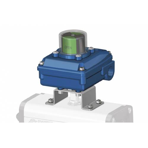
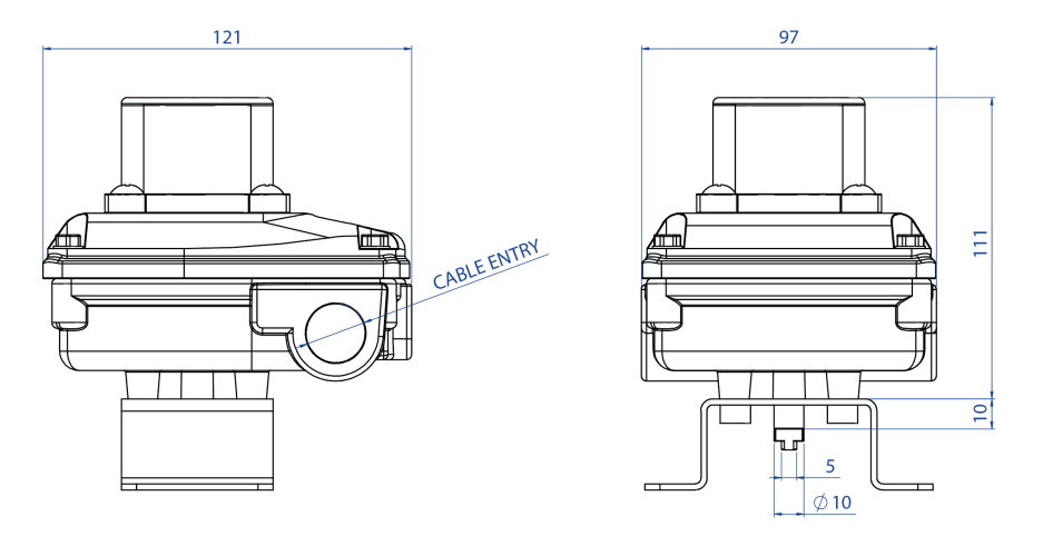
TECHNICAL FEATURES
- Made to easily verify the visual and electrical position of each valve even from long distances.
- Built according to VDI / VDE 3845 standards. (EN15714-3).
- It can contain two limit switches either mechanical "SPDT" or proximity.
- Precise cam adjustment via "Miller" system.
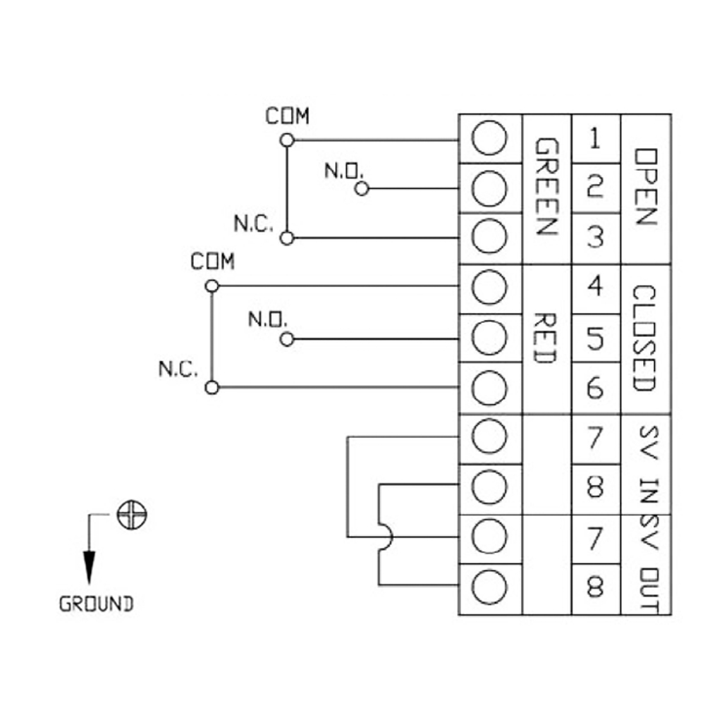
- 8 positions terminal block.
- N. 2 threaded electrical connections for cable gland.
- Operating temperature: from -20°C to + 80°C (NBR).
- Protection rate: IP 67.
MATERIALS
- Body and cover: Copper Aluminum Die Coated with Double blue Epoxy Coating*.
- Indicator: polycarbonate and ABS.
- Shaft: Stainless steel.
- Screws: Stainless steel.
* Also in stainless steel CF8M on request.
CERTIFICATIONS
- CE declaration of conformity on request.
- On request ATEX
- Up to SIL 2 Certified
TYPES OF LIMIT SWITCHES CONTAINED IN BOX KS1L
| CODE* | DESCRIPTION | VERSION | WIRING DIAGRAM |
|---|---|---|---|
| M0 | SPDT Electromechanical microswitches with silver plated contacts (OMRON SS-5) Max: 250 Vac 3A - 125 Vac 5A - 125 Vdc 0,4A |
Standard | ![]() |
| M1 | SPDT Electromechanical microswitches SPDT with gold plated contacts (OMRON SS-01) Max: 125 Vac 0.1A - 30 Vdc 0.1A |
On request | |
| H1 | Hermetically sealed SPDT magnetic proximity switches (HAMLIN 59140) Max: 120 Vac 0.18A - 175 Vdc 0.25A |
On request | |
| 60 | 2-wire NAMUR proximity limit switches SJ 3.5 N P+F, NC, nominal voltage 8,2V, (operating voltage 5 25V) EEx ia IIC T6 |
On request | ![]() |
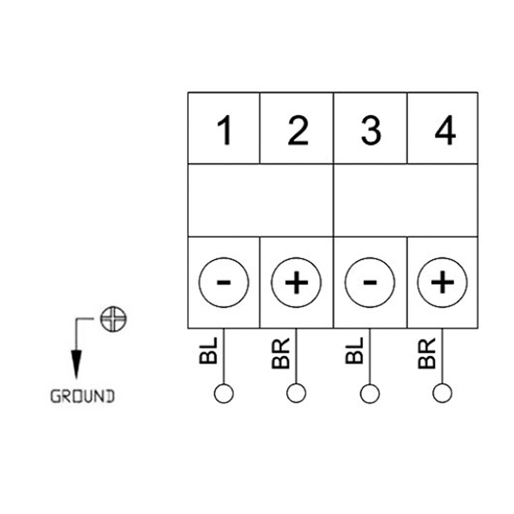
| 70 | 2-wire NAMUR proximity microswitches P + F NJ2 V3 N, NC, 8V EEx ia IIC T6 |
On request | ![]() |
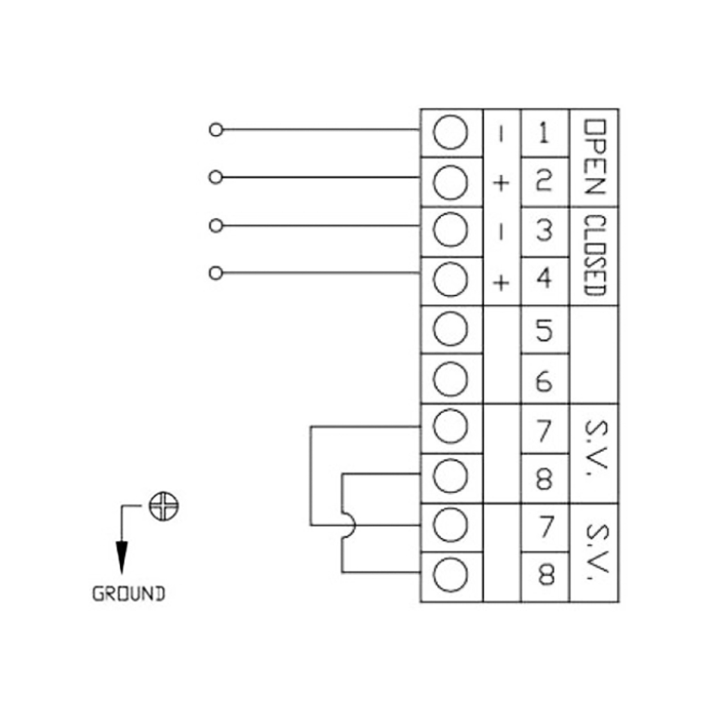
| 73 | 3-wire amplified proximity microswitches PNP NO P+F NBB2 V3 E2, 10÷30 VDC; 100 mA - opereting current 0 - 100 mA |
On request | ![]() |
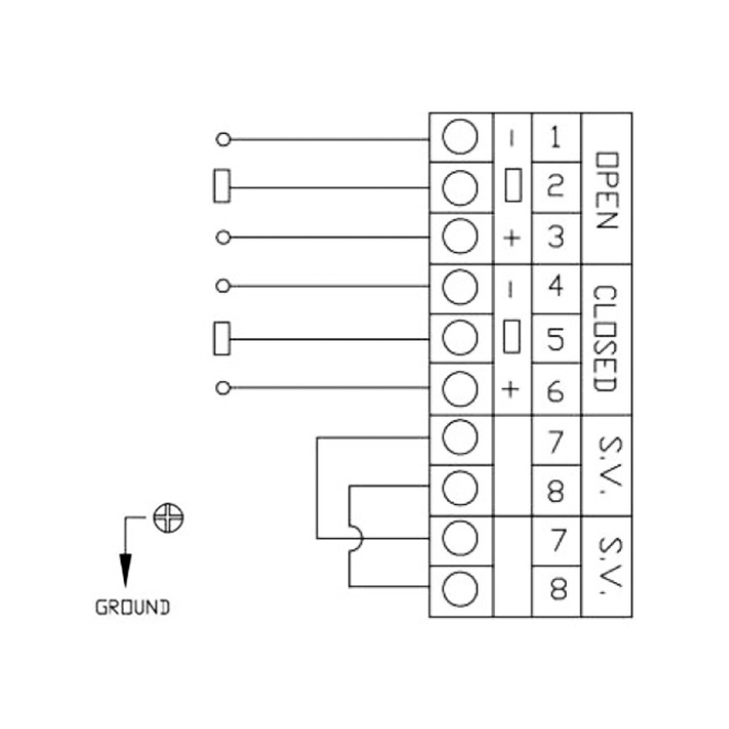
| 75 | 2-wire amplified proximity microswitches IFM IS 5026 5÷36 Vdc; 4÷200 mA |
On request | ![]() |
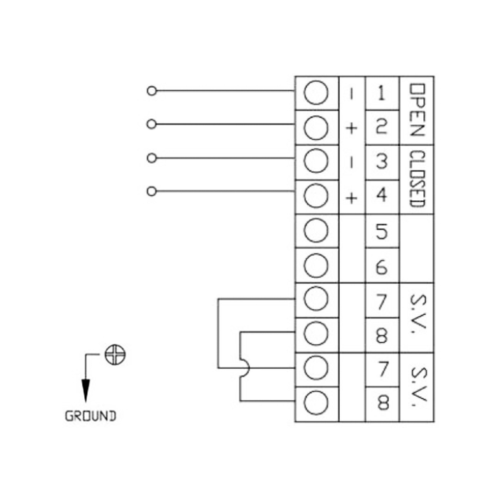
| 78 | 2-wire NAMUR proximity microswitches P + NCB2 V3 NO, NC unamplified, NC, 8.2V EEx ia IIC T6 |
On request |
* The symbol that identifies the type of limit switches used, appears in the code box in the 6th and 7th position.
CONNECTION BRACKET BETWEEN ACTUATOR AND LIMIT SWITCHES BOX
KS1L
| TYPE OF BRACKET* | DESCRIPTION |
|---|---|
| 0 | Namur connection 25x50x20* (*20= height of the actuator shaft, dimension A as per picture) |
| 1 | Namur connection 30x80x20* (*20=height of the actuator shaft, dimension A as per picture) |
| 3 | Namur connection 30x80x30* (*30=height of the actuator shaft, dimension A as per picture) |
| 4 | Namur connection 30x80x30* (*30=height of the actuator shaft, dimension A as per picture) |
| 5 | Namur connection 30x130x30* (*30=height of the actuator shaft, dimension A as per picture) |
| FOR ALUMINIUM ACTUATORS | ||||
|---|---|---|---|---|
| SIZE | DAN15÷DAN120 SRN15÷SRN60 | DAN180÷DAN960 SRN90÷SRN480 | DAN1440÷DAN1920 SRN720÷SRN960 | DA2880÷DA8000 SR1440÷SR4000 |
| Code | KCPL1015 | KCPL1060 | KCPL2060 | KCPL1A04 |
| Type of bracket | 1 | 3 | 4 | 5 |
| A (mm) | 20 | 30 | 30 | 30 |
| B (mm) | 30 | 40 | 40 | 40 |
| C (mm) | 30 | 30 | 30 | 30 |
| D (mm) | 80 | 80 | 80 | 130 |
| FOR STAINLESS STEEL ACTUATORS | ||||
|---|---|---|---|---|
| SIZE | DA15**÷DA30** SR15** | DA60 SR30 | DA120÷DA960 SR60÷SR480 | DA1440÷DA1920 SR720÷SR960 |
| Code | KCPL0015 | KCPL1060 | KCPL2060 | |
| Type of bracket | 0 | 0 | 3 | 4 |
| A (mm) | 20 | 20 | 30 | 30 |
| B (mm) | 30 | 30 | 40 | 40 |
| C (mm) | 25 | 25 | 30 | 30 |
| D (mm) | 50 | 50 | 80 | 80 |
| BOX CABLE ENTRIES THREAD | ||
|---|---|---|
| Type of cable gland thread*** | Description | Notes |
| 1 | 1/2” NPT | ON REQUEST |
| 2 | M 20x1,5 | STANDARD |